Thermal sensing apparatus and computer system incorporating the same

a technology of thermometer and computer system, applied in the direction of thermometer details, instruments, heat measurement, etc., can solve the problems of cooling, needless noise, and irregular power consumption, and achieve the effect of reducing the number of devices

Inactive Publication Date: 2006-12-21
SAMSUNG ELECTRONICS CO LTD
View PDF0 Cites 9 Cited by
  • Summary
  • Abstract
  • Description
  • Claims
  • Application Information

AI Technical Summary

Benefits of technology

[0012] Various aspects and example embodiments of the present invention advantageously provide a thermal sensing apparatus and a computer system incorporating the same for effectively sensing a temperature of a plurality of points within such a computer system using a simple diode module.

Problems solved by technology

Typically, such a consumption of power is not regular and becomes larger in proportion to a load.
Therefore, if the cooling fan is regularly driven regardless of the consumption of power, over cooling can occur, and needless noise can be generated.
As a result, a central processing unit (CPU) and / or peripheral circuit parts consume a great deal of power.
However, it has been difficult for the conventional thermal sensing apparatus as shown in FIG. 1 to employ a structure for sensing the temperature of the plurality of points.
However, the thermal sensing apparatus as described in connection with FIG. 2, for sensing the temperature of the plurality of points must use expensive thermal sensor ICs 1, 2, 3, which in turn raise the cost of production significantly.
As a result, a lot of mounting space on lay-out is required.
Furthermore, the communication arrangement between the thermal sensor ICs 1, 2, 3, and the master sensor IC 7 requires that a realized circuit be complicated.
As a result, the reliability is deteriorated by communication error.

Method used


Image

  • Thermal sensing apparatus and computer system incorporating the same
  • Thermal sensing apparatus and computer system incorporating the same
  • Thermal sensing apparatus and computer system incorporating the same

Examples


first embodiment

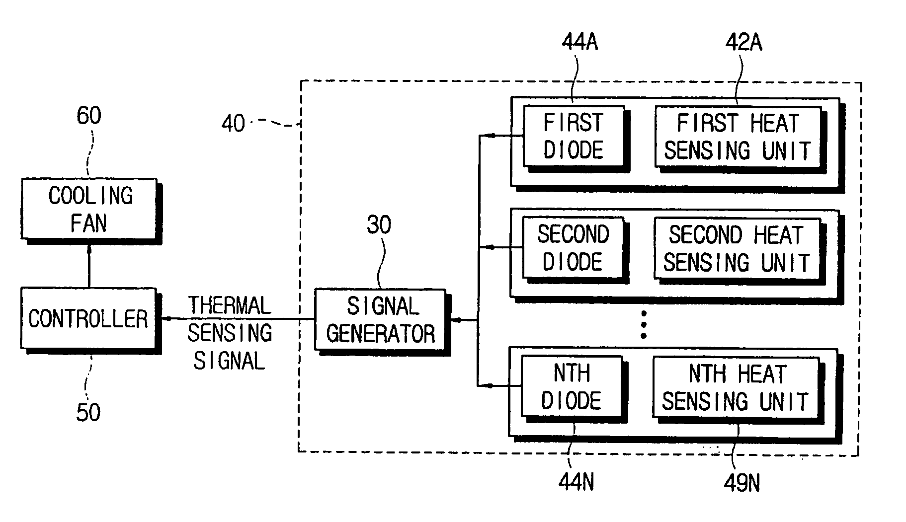
[0043]FIG. 5 is a circuit diagram of an example thermal sensing apparatus 40 for sensing a temperature of a plurality of points according to the present invention. As shown in FIG. 5, the thermal sensing apparatus 40 comprises a plurality of thermistors 10A-10N, which are respectively provided in the plurality of points TH1, TH2, and THn for sensing heat of the plurality of circuit parts 61, 62, 63, 64, 65; a plurality of diodes D1, D2, and Dn each of which is provided in a rear end of each thermistor for intercepting an interference of the plurality of thermistors 10A-10N; and a signal generator 30′ which compares a predetermined standard voltage, which is provided from a power supply source Vcc, and an input signal voltage, which is changed according as at least one of the plurality of diodes D1, D2, and Dn is connected by change of an electric resistance value of the plurality of thermistors 10A-10N, and generates a thermal sensing signal according to a comparison result.

[0044] T...

second embodiment

[0055] Turning now to FIG. 6A, a circuit diagram of an example thermal sensing apparatus for sensing a temperature of a plurality of points or positions in a computer system according to the present invention is illustrated.

[0056] As shown in FIG. 6A, the thermal sensing apparatus 40 comprises a plurality of thermistors 10A-10N, which are respectively provided in a plurality of points TH1, TH2, and THn for sensing heat of a plurality of circuit parts 61, 62, 63, 64, and 65; a plurality of diodes D1, D2, and Dn each of which is provided in a front end of each thermistor for intercepting the interference of the plurality of thermistors 10A-10N; and a signal generator 30″ which compares a predetermined standard voltage provided from a power supply source Vcc and an input signal voltage, which is changed according as at least one of the plurality of diodes D1, D2, and Dn is connected by change of an electric resistance value of the plurality of thermistors 10A-10N , and then generates a...


PUM

PropertyMeasurementUnit
temperatureaaaaaaaaaa
electric resistanceaaaaaaaaaa
voltageaaaaaaaaaa

Abstract

A thermal sensing apparatus is provided with a simple diode module for sensing a temperature of a plurality of points or positions within a computer system. Such a thermal sensing apparatus comprises: a plurality of heat sensing units provided at different points or positions for sensing heat generated from one or more sensing subjects; a plurality of switching units connected to the plurality of heat sensing units; and a signal generator which compares a predetermined standard voltage and an input signal, which is changed when at least one of the plurality of switching units turns on, based on a sensing result from the plurality of heat sensing units, and generates a predetermined thermal sensing signal according to a comparision result.

Description

CROSS-REFERENCE TO RELATED APPLICATIONS [0001] This application claims all benefits accruing under 35 U.S.C. §119 from Korean Patent Application No. 2005-52083, filed on Jun. 16, 2005 in the Korean Intellectual Property Office, the disclosure of which is incorporated by reference herein. BACKGROUND OF THE INVENTION [0002] 1. Field of the Invention [0003] The present invention relates to a thermal sensing apparatus, and more particularly, to a thermal sensing apparatus and a computer system incorporating the same for effectively sensing a temperature of a plurality of points within the computer system. [0004] 2. Related Art [0005] Generally, a computer system includes a cooling fan to cool heat generated by consumption of power. Typically, such a consumption of power is not regular and becomes larger in proportion to a load. Therefore, if the cooling fan is regularly driven regardless of the consumption of power, over cooling can occur, and needless noise can be generated. [0006] The...

Claims


Application Information

Patent Timeline
Patent Type & Authority Applications(United States)
IPC IPC(8): G01K1/14
CPCG01K1/026G01K7/16G01K3/005G06F1/20
Inventor PARK, JEONG-GYU
Owner SAMSUNG ELECTRONICS CO LTD
Why Eureka
Try Eureka