Hex tube light homogenizer splitter

a technology of light homogenizer and hexagonal glass rod, which is applied in the direction of optical elements, planar/plate-like light guides, instruments, etc., can solve the problems of high manufacturing cost, high manufacturing cost, and inability to bend optical fibers,

Inactive Publication Date: 2006-12-21
THE BOEING CO
View PDF26 Cites 12 Cited by
  • Summary
  • Abstract
  • Description
  • Claims
  • Application Information

AI Technical Summary

Problems solved by technology

Generally, it is not possible to bend an optical fiber, for example, at a 90° angle.
The hexagonal glass rod needs to be highly polished on both ends and needs to be coated on the outside with a highly reflective coating, which creates high manufacturing cost.
Furthermore, the hexagonal glass rod is highly fragile and needs to be handled carefully, which might be difficult to realize in industrial applications.
Still further, the light passing through the hexagonal glass rod may lose some of its intensity and the hexagonal glass rod cannot be adjusted to different wavelengths.
Fiber optic couplers attenuate the signal resulting in a loss of intensity because the input signal is divided among the output ports.
However, an optical splitter may distribute the optical power carried by input power in an uneven manner.
Usually, optical splitters have low transmission efficiency resulting in a loss of optical power due to their design.

Method used


Image

  • Hex tube light homogenizer splitter
  • Hex tube light homogenizer splitter
  • Hex tube light homogenizer splitter

Examples


Embodiment Construction

[0018] The following detailed description is of the best currently contemplated modes of carrying out the invention. The description is not to be taken in a limiting sense, but is made merely for the purpose of illustrating the general principles of the invention, since the scope of the invention is best defined by the appended claims.

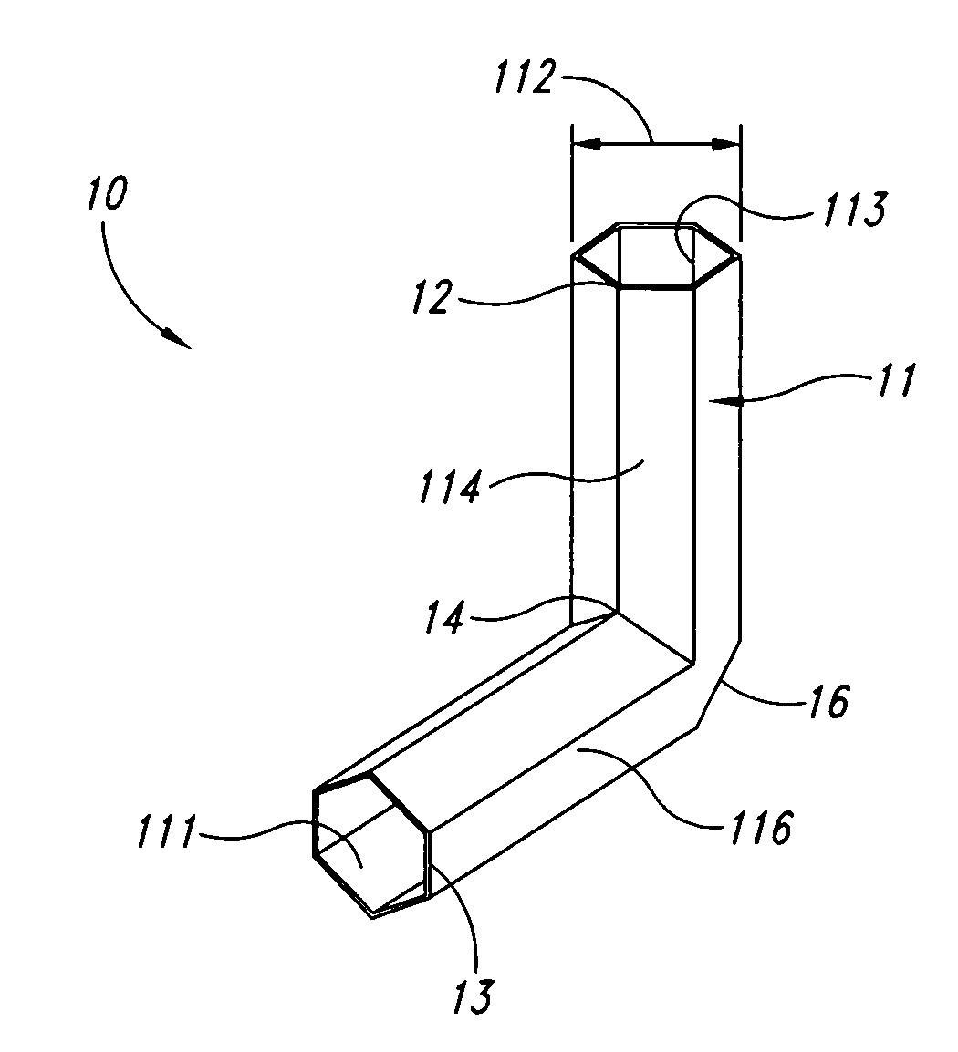
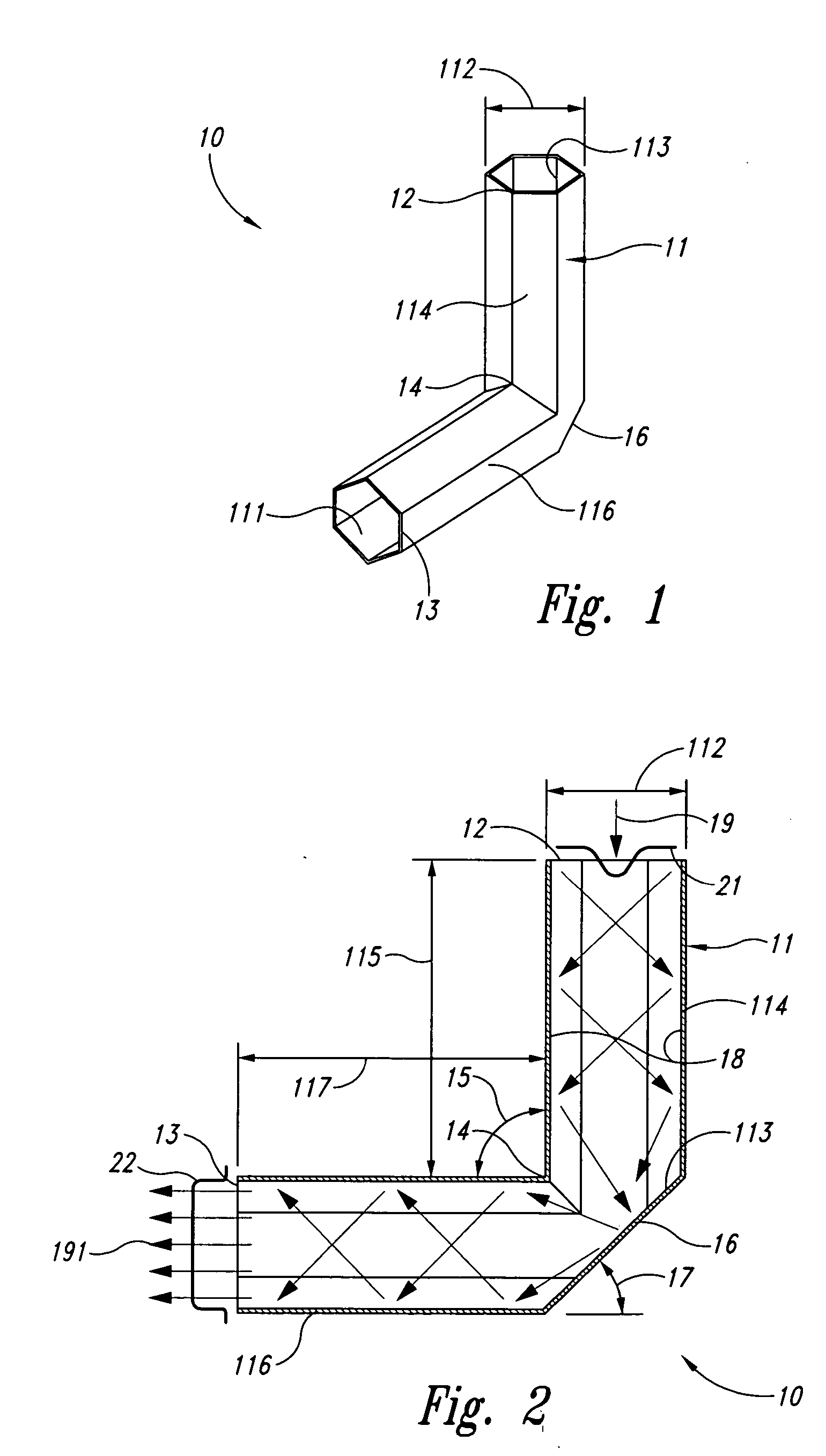
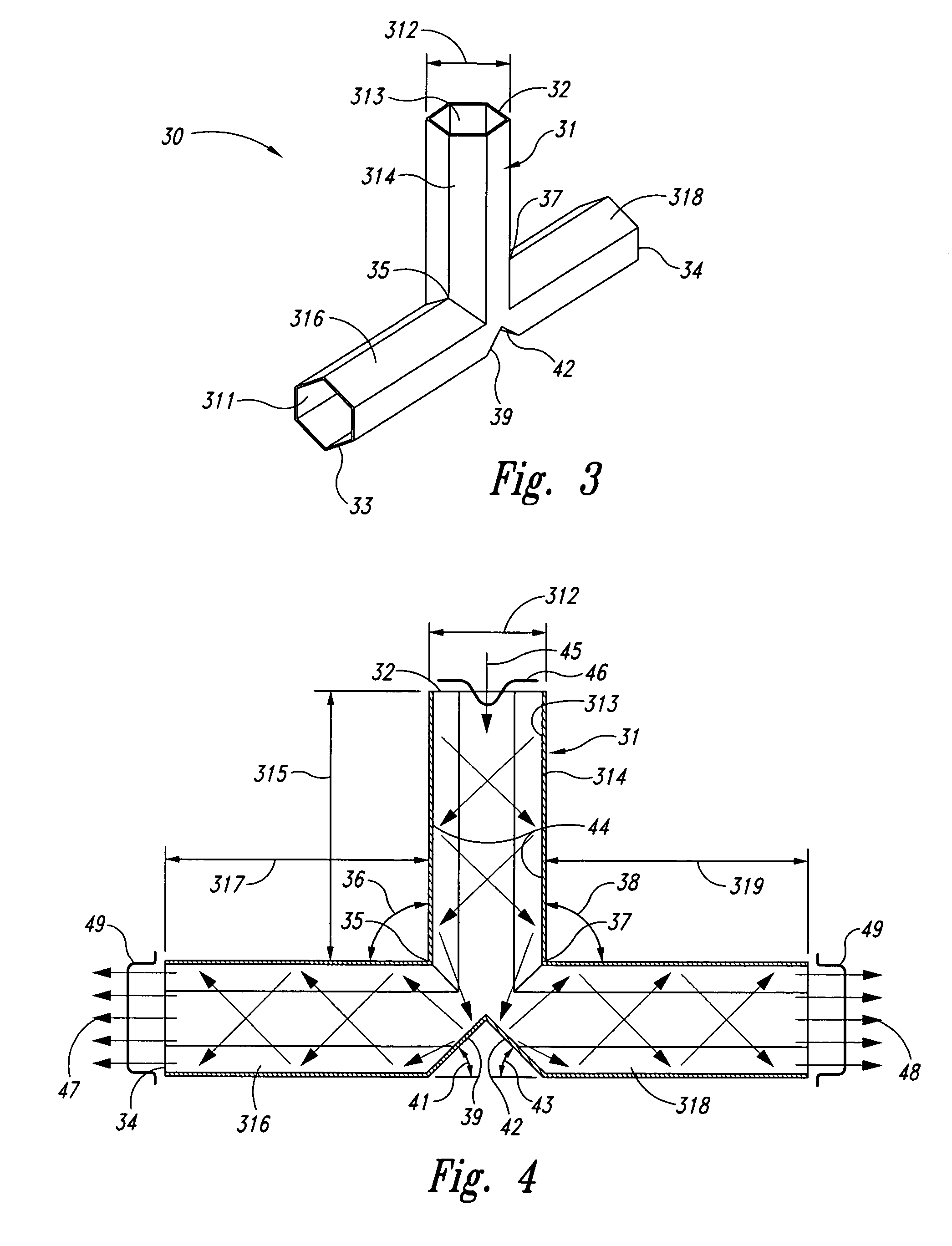
[0019] Broadly, the present invention provides a right angle light diverter that enables bending a light beam at a right angle as well as producing and maintaining a homogenous profile of a light beam while redistributing the optical energy. An embodiment of the present invention provides a right angle light diverter that is suitable for, but not limited to, applications in aircraft industry, both military and commercial. The right angle light diverter as in one embodiment of the present invention may be used, for example, in connection with airborne laser programs, with airborne tactical laser programs, in commercial airplanes, and in military jets, ...


PUM


Abstract

A right angle light diverter includes a hexagonal tube that is bent at a right angle that is coated with a highly reflective coating on the inside surface. An incoming light beam may be homogenized upon entering an input port of the hexagonal tube and may be evenly diverted at a right angle at a reflection section while the homogenized profile may be maintained. A right angle optical splitter may include at least one additional output section. An incoming light beam may be homogenized and may be split into at least two outgoing beams that may be diverted at right angles at reflection sections. The right angle light diverter and the right angle optical splitter may be suitable for, but not limited to, applications in aircraft industry, both military and commercial. They may be used, for example, in connection with airborne laser programs, in commercial airplanes, and in military jets.

Description

CROSS REFERENCE TO RELATED APPLICATIONS [0001] The present application is a continuation application of U.S. patent application Ser. No. 11 / 154,079, filed Jun. 15, 2005. The present application is related to the following co-pending United States patent application: “Hex Tube Light Homogenizer System and Method”, Ser. No. 10 / 744,922, filed Dec. 23, 2003.BACKGROUND OF THE INVENTION [0002] The present invention generally relates to light transmitting devices and systems and, more particularly, to a right angle light diverter, to a right angle optical splitter, and to a method for splitting an initial light source into numerous light beams. [0003] Optical fibers are transparent thin fibers, such as long, thin strands of optically pure glass, for transmitting light. Typically, optical fibers are arranged in bundles, such as optical cables, and are used in various industries to transmit light or light signals, such as digital information, over long distances. Generally, two types of opti...

Claims


Application Information

Patent Timeline
Patent Type & Authority Applications(United States)
IPC IPC(8): G02B6/10
CPCG02B6/0018G02B6/0096G02B6/262G02B27/143G02B27/0927G02B27/0994G02B27/106G02B6/2817
Inventor CIANCIOTTO, FRANKBUTLER, GEORGE
Owner THE BOEING CO
Why Eureka
Try Eureka