Fuel cell, fuel cell stack, and fuel cell system

Inactive Publication Date: 2006-12-21
DENSO CORP
View PDF3 Cites 13 Cited by
  • Summary
  • Abstract
  • Description
  • Claims
  • Application Information

AI Technical Summary

Benefits of technology

[0025] Therefore the configuration of the fuel cell and the fuel cell stack according to the present invention is capable of exhausting the residual water efficiently by the gravity without heating the fuel cell stack after the stoppage of

Problems solved by technology

However, it is undesirable to heat the fuel cell stack by the electricity generation using hydrogen gas because a driver usually leaves a vehicle equipped with the fuel cell system.

Method used


Image

  • Fuel cell, fuel cell stack, and fuel cell system
  • Fuel cell, fuel cell stack, and fuel cell system
  • Fuel cell, fuel cell stack, and fuel cell system

Examples


Example

[0037] Hereinafter, various embodiments of the present invention will be described with reference to the accompanying drawings. In the following description of the various embodiments, like reference characters or numerals designate like or equivalent component parts throughout the several diagrams.

Embodiments

[0038] A description will now be given of the fuel cell and the fuel cell system according to various embodiments of the present invention.

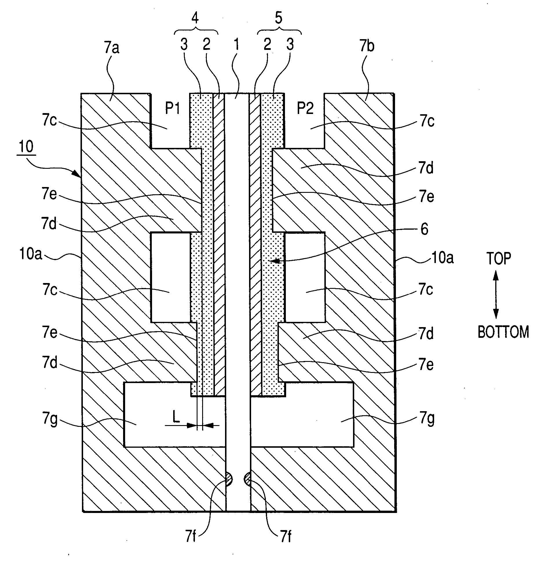
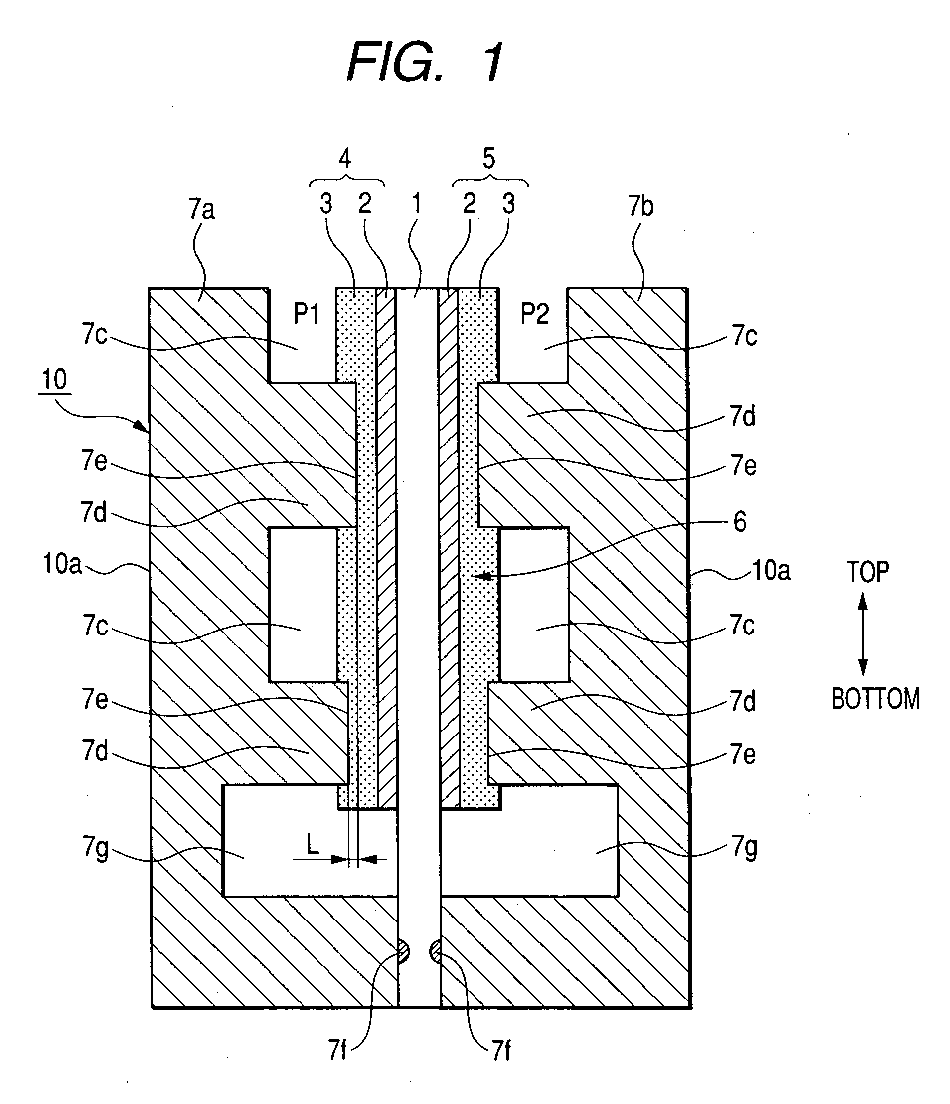
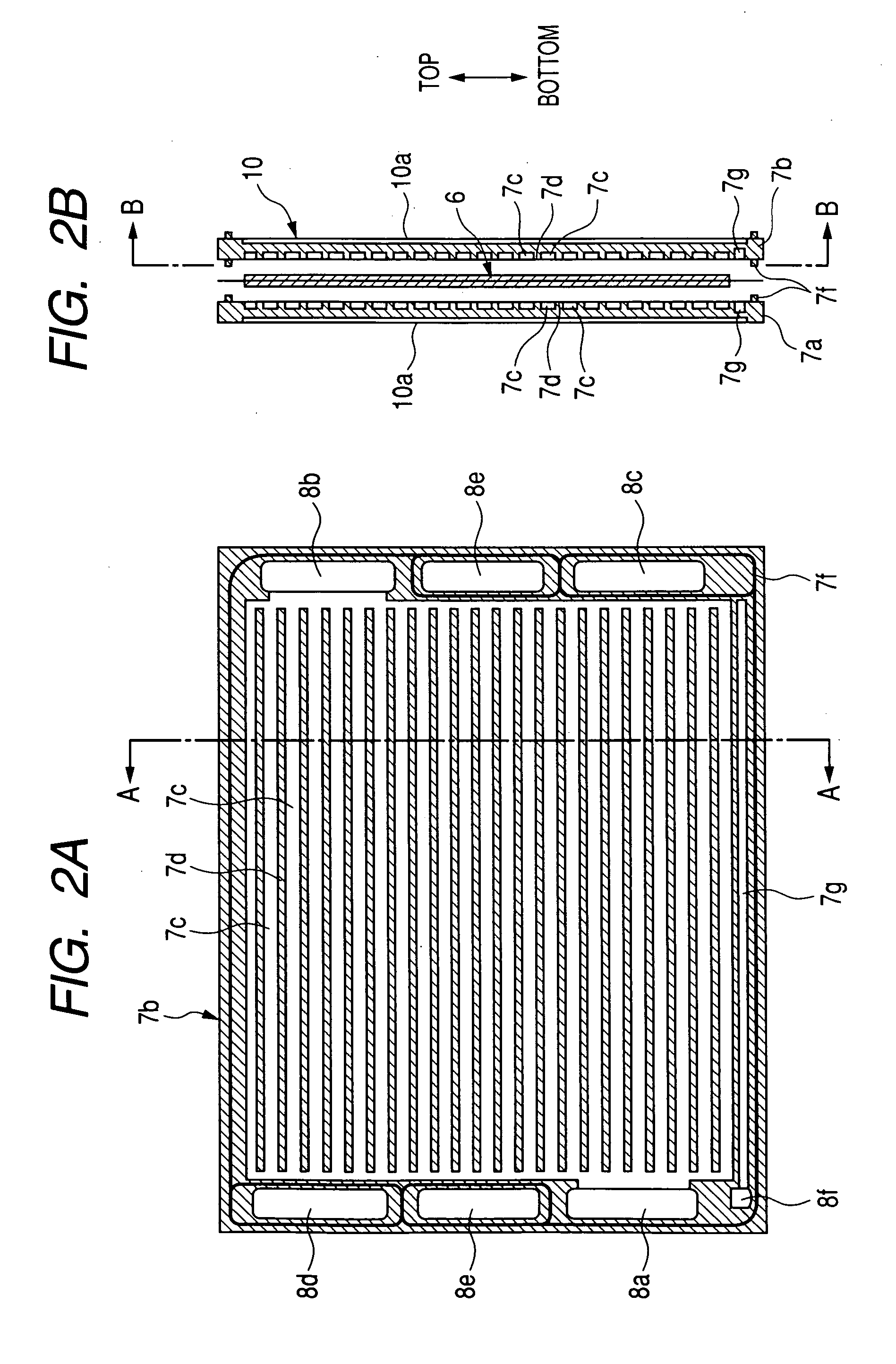
[0039]FIG. 1 is a schematic sectional view showing a configuration of a part of the fuel cell in a solid polymer proton-conducting cation-exchange electrolyte membrane fuel cell (PEFC) that forms the fuel cell stack 100 (see FIG. 3) according to an embodiment of the present invention. FIG. 2A is a schematic sectional view showing the inside configuration of one separator forming the fuel cell shown in FIG. 1. FIG. 2B is a schematic sectional view showing the configuration of the fuel cell along A-A line in FIG. 2A.

[0040] In particular, F...


PUM


Abstract

A fuel cell stack has plural fuel cells stacked in series along a direction vertical to a main surface of each fuel cell. Each fuel cell has a lamination body made of an anode, a cathode, and a polymer proton exchange membrane. The lamination body is sandwiched between a pair of separators. Each of the anode and cathode has a catalyst layer and a diffusion layer laminated. A water collecting groove and fuel gas passages are formed in the inner surface of each separator. The bottom end of the water collection groove is lower in position than the end of the catalyst layer and the diffusion layer. The water collecting groove is not joined to the fuel gas passages and collects water produced by electrochemical reaction in each fuel cell, and drains the collected water.

Description

CROSS-REFERENCE TO RELATED APPLICATIONS [0001] This application is related to and claims priority from Japanese Patent Application No. 2005-174987 filed on Jun. 15, 2005, the contents of which are hereby incorporated by reference. BACKGROUND OF THE INVENTION [0002] 1. Field of the Invention [0003] The present invention relates to a fuel cell, so-called a solid polymer proton-conducting cation-exchange electrolyte membrane fuel cell (PEFC), a fuel cell stack composed of a plurality of the fuel cells stacked in series, in which the fuel cell consists of a polymer proton exchange membrane sandwiched between two electrodes, anode and cathode, and further relates to a fuel cell system equipped with the fuel cell stack that is suitably applicable to movable bodies, such as electric vehicles (or fuel cell vehicles) using a fuel cell as an electric power source. [0004] 2. Description of the Related Art [0005]FIG. 5 is a schematic sectional diagram showing a configuration of a part of a fuel...

Claims


Application Information

Patent Timeline
IPC IPC(8): H01M8/02H01M8/10H01M4/94H01M8/24
CPCH01M8/0234H01M8/0247Y02E60/521H01M8/04156H01M8/1002H01M8/0258H01M8/0267H01M8/241H01M8/1007H01M8/2457H01M8/2483Y02E60/50
Inventor KIKUCHI, TETSUROUSAMI, HIROYUKIKUDO, HIROYASUSAKAJO, YUICHI
Owner DENSO CORP
Why Eureka
Try Eureka