Watertight decking

a technology of extruded panels and decking, which is applied in the field of extruded panels, can solve the problems of general unsuitability of extruded panels for use as decks or roof surfaces, limited maximum width, and inability to withstand water, so as to prevent capillary flow or “wicking” and prevent noise from contact. , the effect of adding strength

Inactive Publication Date: 2006-12-28
REED BOBBY
View PDF31 Cites 60 Cited by
  • Summary
  • Abstract
  • Description
  • Claims
  • Application Information

AI Technical Summary

Benefits of technology

[0030] The second side and central panels also include depending drip rails, which extend downwardly into the gutter of the adjoining panel. These drip rails serve two functions: (1) they prevent capillary flow or “wicking” of any moisture which seeps through the joints between panels from flowing along the underside of the panel and past the opposite gutter wall to drip into the underlying room or area, and (2) the drip rails are spaced to produce a wedging fit against the gutter wall edge of the adjoining panel, forcing the tongue and groove joint tightly together. The gutter wall against which the drip rail bears is preferably somewhat shorter than the underside of the adjoining panel installed thereover, in order to prevent noise from contact between the gutter wall and the overlying panel when the assembly is walked upon and flexed slightly.
[0031] Additional sealing may be provided in the form of a resilient seal disposed within the groove of the tongue and groove joints between the panels, in order to further insure against moisture penetration through the panel assembly. Also, the depending drip rail may have a be

Problems solved by technology

Moreover, wood is not particularly durable when used as a deck surface or in other areas where considerable wear and tear may occur, and at the very least must be treated in some manner (pressure treatment, paint, etc.) in order to resist deterioration due to moisture.
However, the fact that such panels are somewhat limited in their maximum width due to constraints involved in the extrusion process and shipping, results in the need to assemble a series of such extrusions together in order to provide the desired width for most deck installations.
While such an assembly can be constructed to form a structurally sound installation, the slight gaps between the assembled panels generally allow rain or other moisture to pass therethrough.
Thus, such extruded panels are generally unsuitable for use as a deck or roof surface overlying a room or other area which must be kept dry, unless additional waterproofing in the form of an underlying substructure covered with tarpaper, plastic sheeting, or some other waterproof material, is provided.
While some attempts have been made to form extrusions that provide a truly waterproof joint, the fact remains that none of the decking extrusions of which the present inventors are aware provide a truly waterproof surface when assembled.
When such extruded panels are used to cover an underlying room or the like, the unfinished appearance of the underlying exposed surfaces of the panels is unattractive.
Moreover, the relatively thin single wall, sheet or ply of the upper surface of the panels provides practically no insulation.
The Simpson roof panels are so thin and light, that they cannot support the weight of a person thereon by themselves.
Simpson does not provide any form of drain channels beneath his roof panels.
However, the interlocking portions are upstanding when the panels are used for roofing.
The raised interlocked edges render the Oehlert panels unsuitable for use as a deck for walking upon.
In any event, the thin sheet metal from which the Oehlert panels are formed do not provide sufficient structural strength to serve as a deck.
While Oehlert does provide channels within the interlocked edges of his panels, they are not waterproof, as fasteners are driven through the floors of the channels to anchor the assembly to the underlying structure.
Oehlert does not provide any secondary bottom surface for his panels.
Moreover, the thin sheet metal of the Tor panels do not provide sufficient structural strength for walking upon and/or supporting relatively heavy articles, e.g., outdoor furniture, etc., as would normally be found on a deck.
Tor does not provide a bottom surface opposite the upper surface of his panels to define a conduit or other utility space therebetween.
The panels of the Hallsten structure interl

Method used


Image

  • Watertight decking
  • Watertight decking
  • Watertight decking

Examples


first embodiment

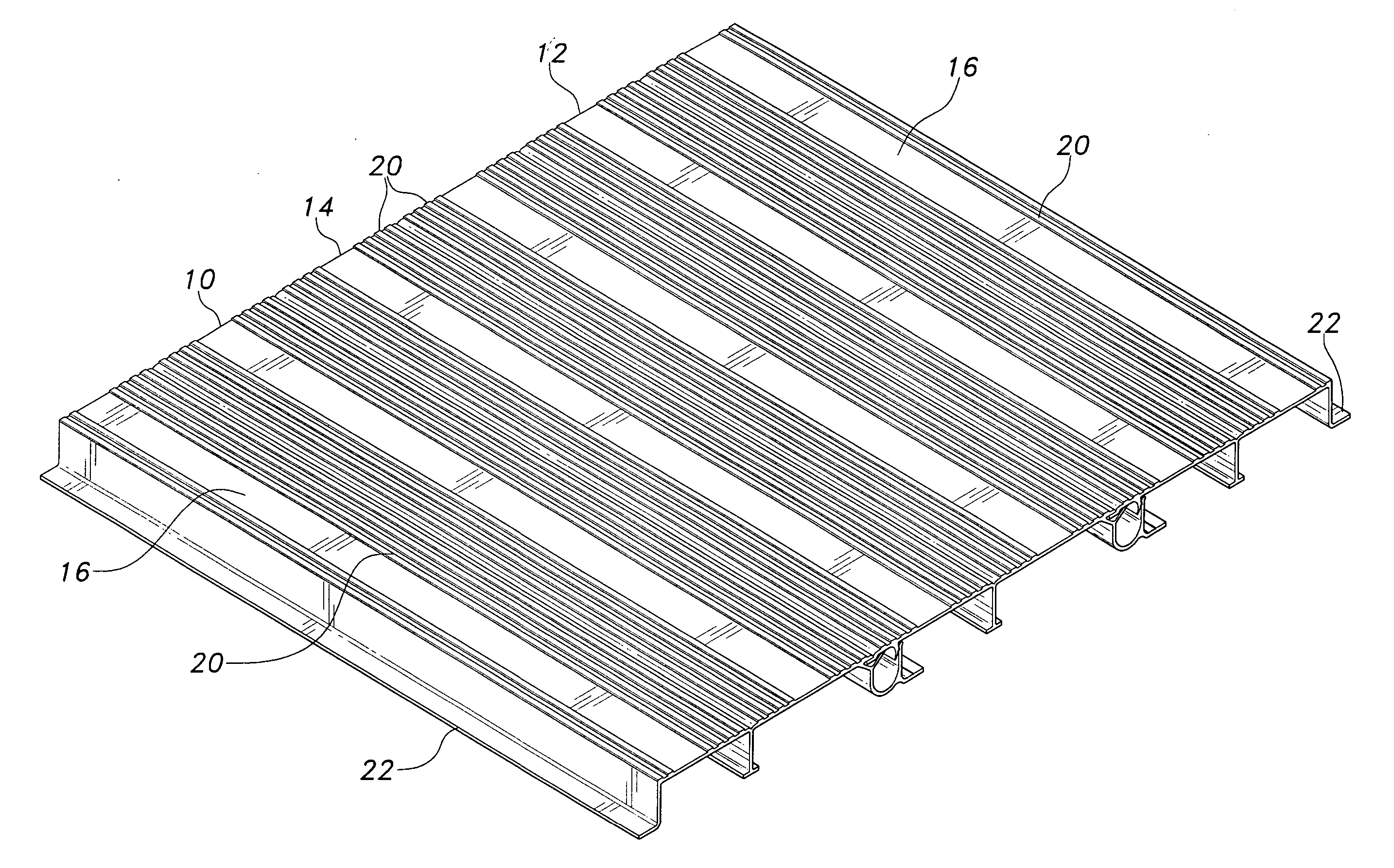
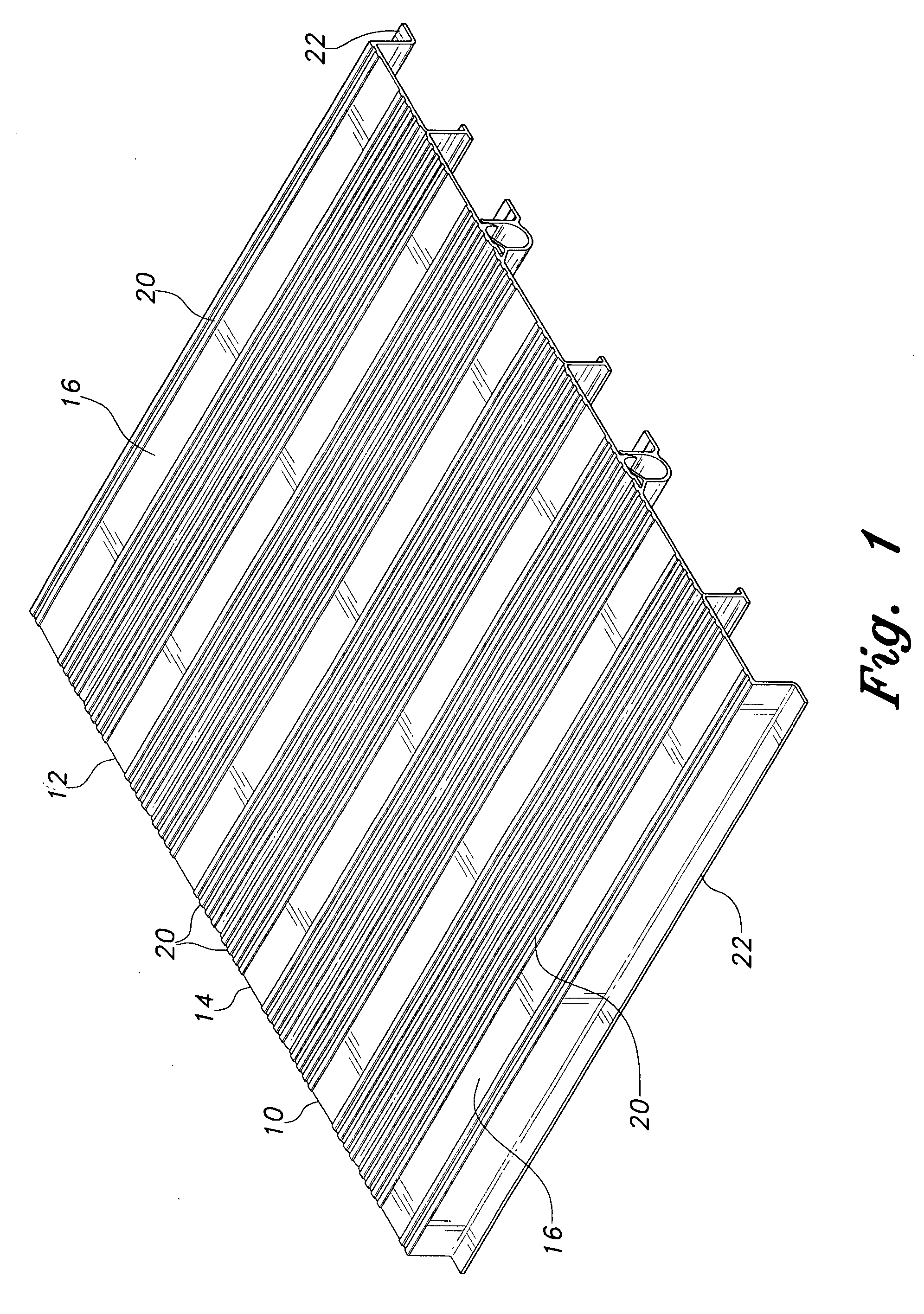
[0059]FIG. 1 of the drawings provides a perspective view of a panel assembly formed of a series of first embodiment panels, comprising a first end panel 10, a second end panel 12, and an intermediate panel 14. Each of the panels 10 through 14 includes a single wall or ply having a generally flat, planar upper surface 16 and an opposite lower or bottom surface 18 (shown in FIG. 3). The upper surface may be provided with ribs 20 (or other raised or recessed pattern) to provide more secure traction when walking on a deck formed of the present panels. The first and second end panels 10 and 12 each include finished, flanged outboard edges 22, which are not configured to attach to other panels of the present invention. However, the first end panel 10 and intermediate panel 14 each have first attachment edges which positively interlock with the mating second attachment edges of second end panel 12 and other intermediate panels 14 (not shown).

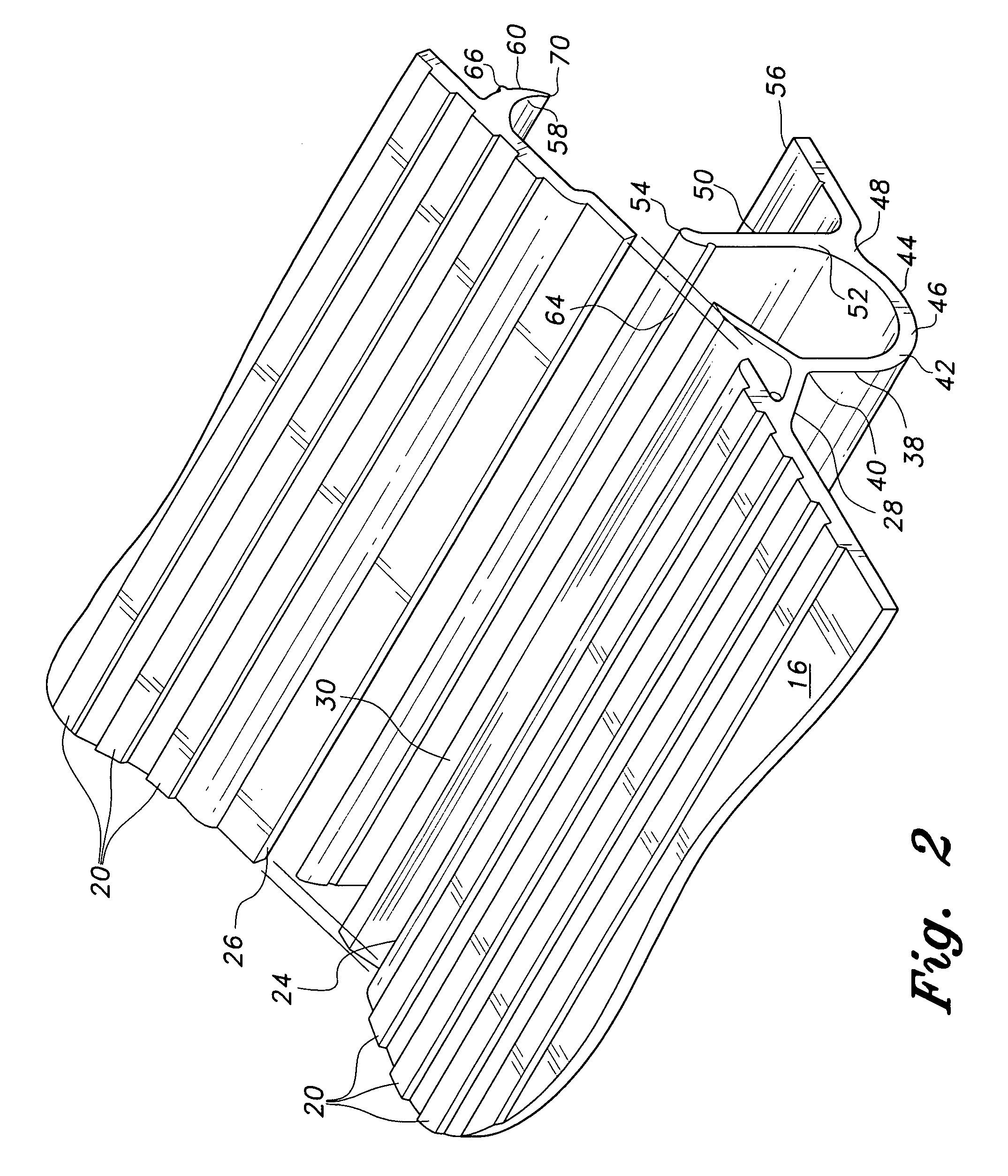
[0060]FIGS. 2 and 3 respectively provide explode...

seventh embodiment

[0080] The seventh embodiment panels of FIGS. 10 through 12 are configured particularly well for providing passage of various fluids for heating or cooling the panels, or for other purposes as desired. Accordingly, one or more pipe fittings, conduits, and / or manifolds may be secured to the ends or edges of the panels 710 through 714, as shown in FIG. 11. A manifold 772 is shown to the left in FIG. 11, separated from the panel assembly in order to show various details. The manifold 772 comprises a continuous plate 774 having a series of tubes or pipes 776 which plug into the corresponding conduits or passages 729 of the panels. Each of the pipes 776 preferably includes an O-ring 778 or other suitable seal to preclude leakage between the pipes 776 and conduits 729. A series of screws 780 engages corresponding screw slots 782, more clearly shown in the detail of FIG. 12, to secure the manifold plate 774 in place on the panel(s).

[0081] Alternatively, single fittings may be used, e.g. th...

ninth embodiment

[0093]FIG. 23 illustrates a cross section of a fifteenth embodiment of the watertight decking panels, with the panels of FIG. 23 having upper walls 1517 and opposite lower walls 1521. It will be noted that the fifteenth embodiment of FIG. 23 is similar to FIG. 14, in that the drawings of the embodiments of FIGS. 14 and 23 illustrate common alternative wall configurations 38, 38a, 38b for the channel, as well as an alternative tongue and groove joint assembly common to both of the embodiments of FIGS. 18 and 23. However, it will be noted that the panel embodiment of FIG. 23 includes a continuous, solid lower wall 1521, with its opposite surfaces 1523 and 1525, in keeping with the continuous, solid lower walls of all of the panel embodiments following those of FIGS. 1 through 5.

[0094] In conclusion, the present watertight decking embodiments provide a positive means of sealing a deck or other surface to prevent the passage of moisture therethrough, without any other steps being requir...


PUM

PropertyMeasurementUnit
Pressureaaaaaaaaaa
Flow rateaaaaaaaaaa
Areaaaaaaaaaaa

Abstract

The watertight decking is assembled from extruded panels to form a watertight deck assembly. First side, second side, and intermediate panels have complementary edges mating with other corresponding panels. One edge of the first side and intermediate panels has a drainage gutter and the tongue or groove of a tongue and groove connection, with mating second side and intermediate panel edges having the mating tongue or groove. A depending drip rail wedges tightly against the opposite gutter wall of the adjoining panel to prevent relative motion between the two, and also to prevent capillary flow of liquid across the underside of the panel where it could leak into the area below. Additional sealing may be provided along the tongue and groove joints. A second, lower wall opposite the upper wall defines a series of conduits therebetween, and also strengthens the panels and provides a finished appearance for the underside.

Description

REFERENCE TO RELATED PATENT APPLICATIONS [0001] This application is a continuation in part of U.S. patent application Ser. No. 11 / 203,163 filed on Aug. 15, 2005, which is a continuation in part of U.S. patent application Ser. No. 10 / 770,481 filed on Feb. 4, 2004 and issued on Apr. 4, 2006 as U.S. Pat. No. 7,026,012, incorporated herein by reference in its entirety.BACKGROUND OF THE INVENTION [0002] 1. Field of the Invention [0003] The present invention relates generally to extruded panels, and more particularly to a series of panel extrusions configured to interlock tightly and immovably with one another, and also to preclude moisture passage through the joints between panels. The present watertight decking may be installed as a deck or similar surface over a room, storage area, or other space that must be kept dry, and thereby serves dual purposes as flooring and as a waterproof roof structure over the underlying area. The undersides of the panels may include a bottom surface defin...

Claims


Application Information

Patent Timeline
IPC IPC(8): E04F15/00E04B1/70E04F11/16E04F15/10E04F17/00E04F17/04
CPCE04F15/06E04F15/10F24D3/16E04F2203/04E04F2290/023E04F2201/0153E04F15/02161E04F15/02194E04F15/105Y02B30/00
Inventor ZENG, KARLREED, BOBBY
Owner REED BOBBY
Why Eureka
Try Eureka