Filter vial with limited piston stroke

a filter vial and piston stroke technology, applied in the direction of filtration separation, separation process, laboratory glassware, etc., can solve the problems of filter cracking, leakage, contaminating the filtered fluid in the piston, etc., and achieve the effect of preventing wicking or leakag

Inactive Publication Date: 2015-03-19
SCI PLASTIC PRODS
View PDF10 Cites 11 Cited by
  • Summary
  • Abstract
  • Description
  • Claims
  • Application Information

AI Technical Summary

Benefits of technology

[0007]The filter vial and piston assembly may use a cup which fits over the distal end of the filter to hold the piston filter in position on the piston during use so that all the fluid passes through the filter and none passes around the edges of the filter. The parts forming the piston assembly are preferably integrally molded of one piece of material and may snap together so that there is no contamination from ultrasonic welding. If the parts snap-fit together, appropriates seals are provided to prevent wicking or leakage at the location of the snap-lock joints.

Problems solved by technology

In these processes when the piston is forced against the bottom of the vial the dissolved materials are forced into the piston filter and that may cause the filter to crack and leak—thereby contaminating the filtered fluid in the piston.

Method used


Image

  • Filter vial with limited piston stroke
  • Filter vial with limited piston stroke
  • Filter vial with limited piston stroke

Examples


Embodiment Construction

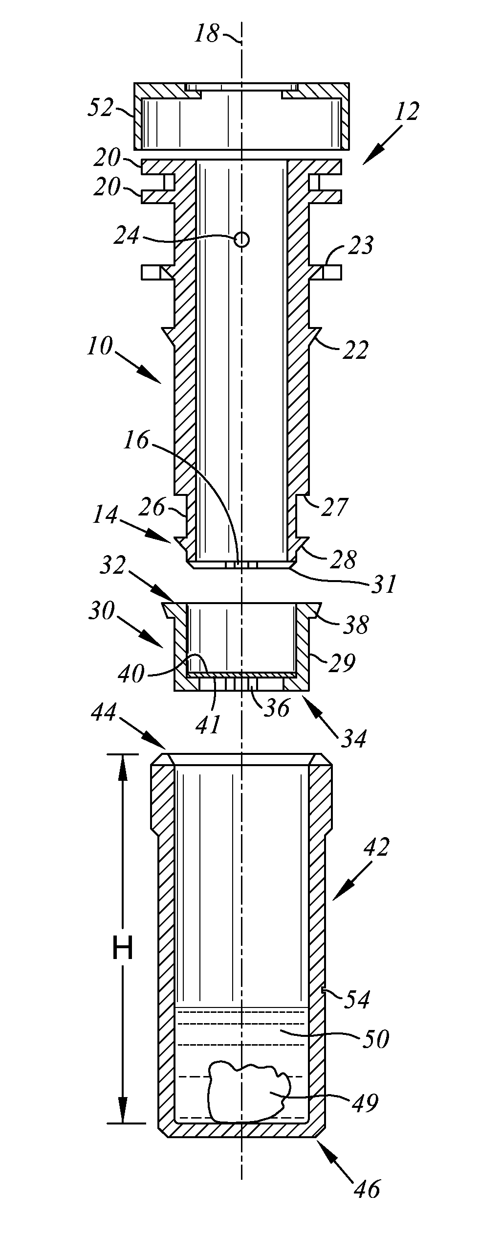
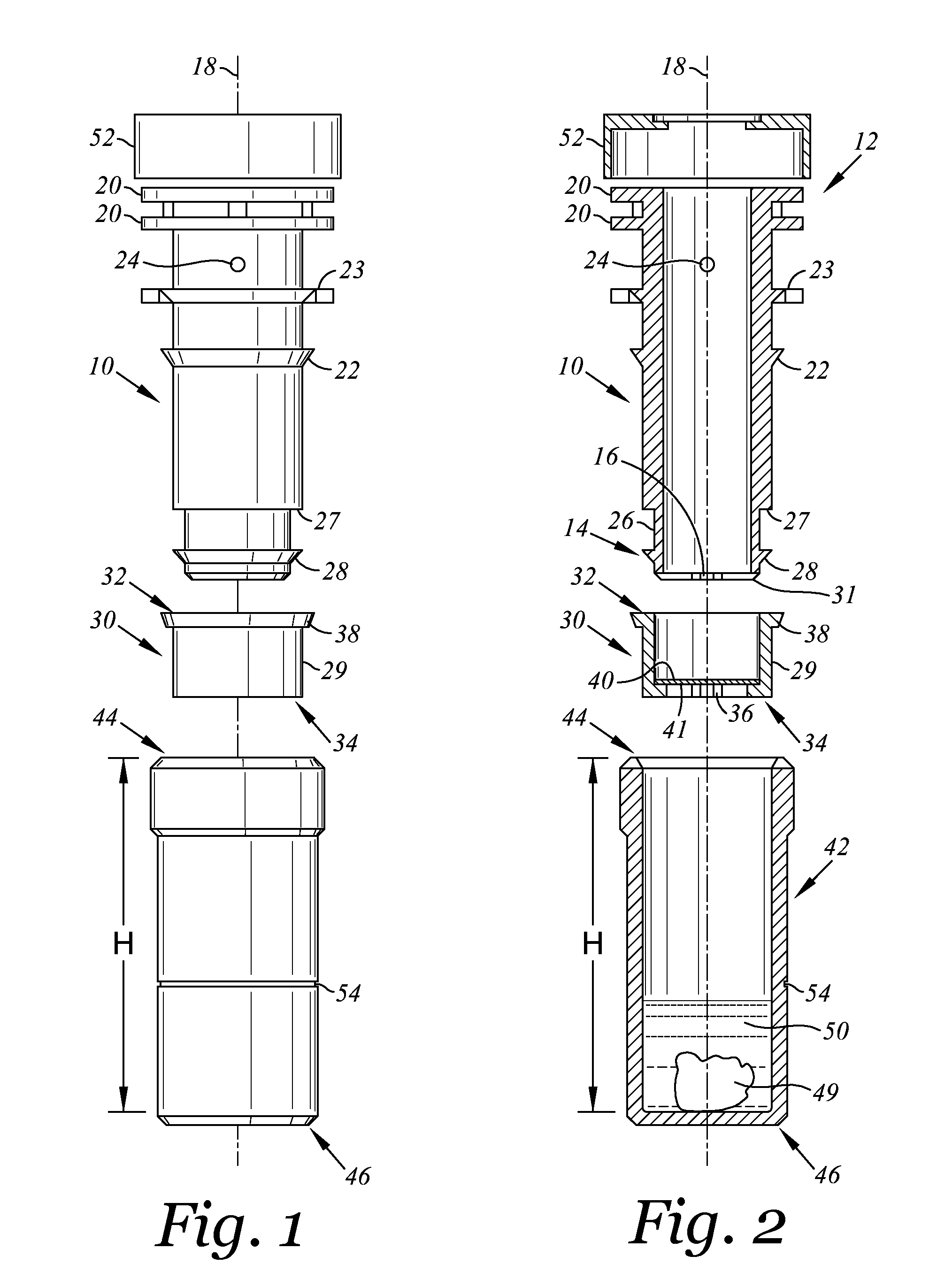
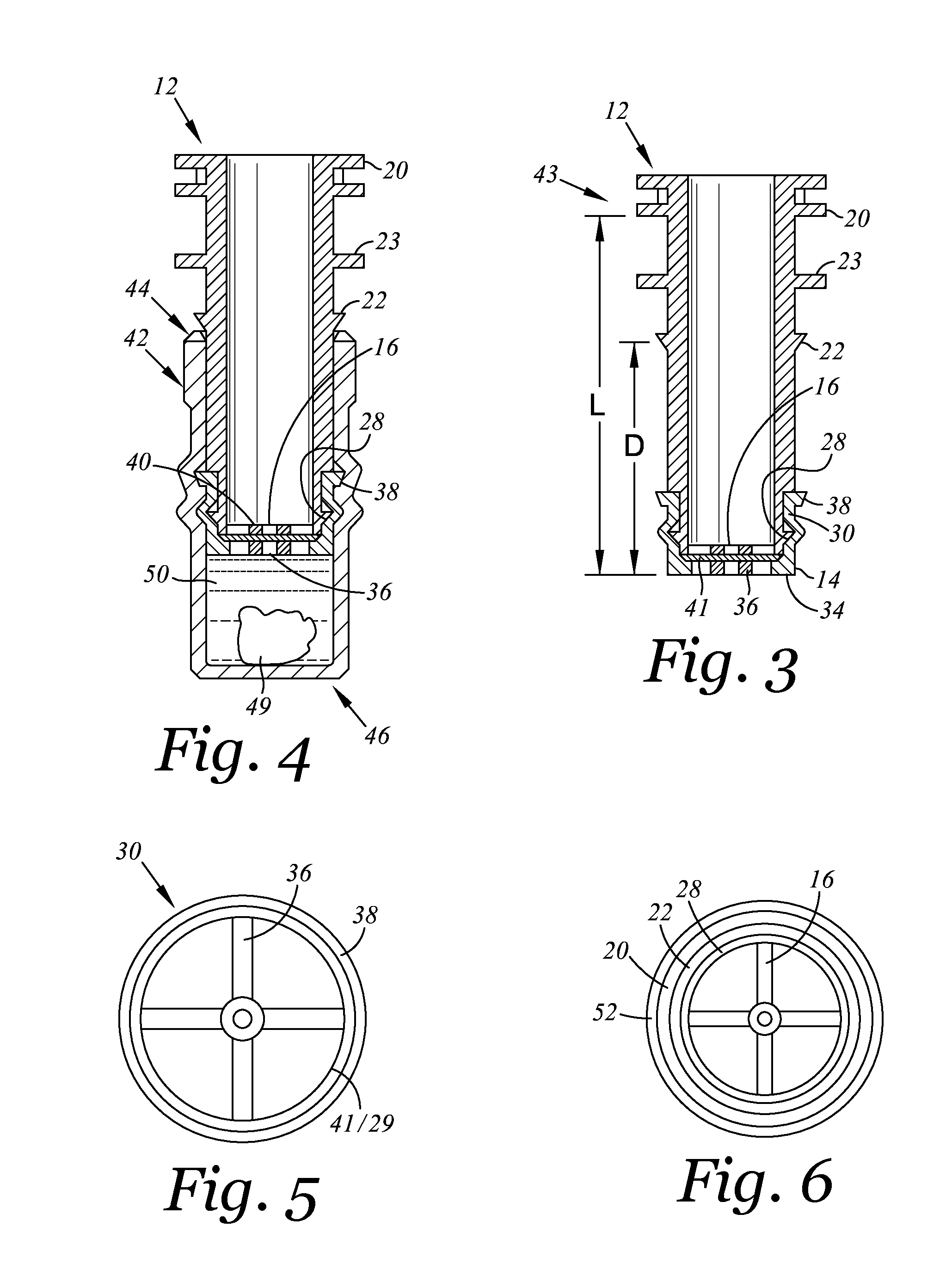
[0030]Referring to FIGS. 1-4, a tubular piston 10 with a circular cross-section has proximal and distal ends 12, 14, respectively, with a porous piston support 16 located at the distal end 14. The support 16 advantageously takes the form of radial arms intersecting at a central location on the longitudinal axis 18 of the piston 10. The terms distal and proximal refer to relative locations of parts along the longitudinal axis 18, and the terms inward and outward refer to relative directions toward and away from the longitudinal axis 18. One or more flanges 20 extend radially from the proximal end 12. A first, proximal seal 22 is located between the proximal and distal ends 12, 14. The first proximal seal 22 extends outward, away from longitudinal axis 18. A vent hole 24 is adjacent the seal 22 and is preferably located slightly toward the proximal end 12 so as to be between the seal 22 and the proximal end 12 of piston 10 as shown in FIG. 1, and preferably between the stop 23 and the...


PUM

PropertyMeasurementUnit
inner diameteraaaaaaaaaa
timeaaaaaaaaaa

Abstract

A filter vial and piston are provided where the vial has a cylindrical wall with a closed bottom and open top and with the hollow, tubular piston therein. The piston has a position stop located and configured to abut a mating position stop on the vial to limit relative movement of the piston and vial. The position stops are located to stop the distal end of the piston away from the bottom of the vial a distance of about 10-30% the height of the vial. That a material to be dissolved in a liquid in the vial and to remove unwanted molecules from the liquid with the piston forcing the liquid through the filter but not squeezing the slurry of material so as to force it into the filter.

Description

CROSS-REFERENCE TO RELATED APPLICATIONS[0001]The application claims the benefit under 35 U.S.C. §119(e) to Provisional Patent Application No. 61 / 877,872 filed Sep. 13, 2013, the entire contents of which are incorporated herein by reference.BACKGROUND[0002]Filter vials have a tubular piston with a filter at the distal end of the piston. The piston fits into a mating vial containing a fluid and things suspended in the fluid. When the piston is inserted into the vial fluid passes through the filter and into the piston in order to separate the fluid from particles or molecules too large to pass through the filter in the bottom of the piston. The filtered fluid can be extracted from the piston for further use. In order to maximize the volume of filtered fluid the filter on the piston is placed at the distal end of the piston and during use that filter is pressed against the bottom of the vial in order to force as much fluid through the filter as possible.[0003]In order to increase the vo...

Claims


Application Information

Patent Timeline
Patent Type & Authority Applications(United States)
IPC IPC(8): B01D36/00B01D33/01B01D15/10
CPCB01D36/00B01D33/0183B01D15/10B01L3/502B01L2300/046B01L2300/0681B01L2300/0832B01L2400/0478
Inventor ELLIS, SAMUEL A.HINGORANI, KISHAN G.
Owner SCI PLASTIC PRODS
Why Eureka
Try Eureka