Apparatus and method for controlling a cryocooler by adjusting cooler gas flow oscillating frequency

a technology of cooler gas flow and apparatus, which is applied in the direction of cooling apparatus, superconducting magnets/coils, instruments, etc., can solve the problems of affecting image quality of mri superconducting magnets and reducing component li

Active Publication Date: 2006-12-28
GENERAL ELECTRIC CO
View PDF11 Cites 19 Cited by
  • Summary
  • Abstract
  • Description
  • Claims
  • Application Information

AI Technical Summary

Problems solved by technology

High oscillation rates designed for maximum cooling capacity increase wear on the sealing components of the cryocooler leading to a reduction in component life.
Large pressure variation in the cryogen p

Method used


Image

  • Apparatus and method for controlling a cryocooler by adjusting cooler gas flow oscillating frequency
  • Apparatus and method for controlling a cryocooler by adjusting cooler gas flow oscillating frequency
  • Apparatus and method for controlling a cryocooler by adjusting cooler gas flow oscillating frequency

Examples


an embodiment

Methods of an Embodiment

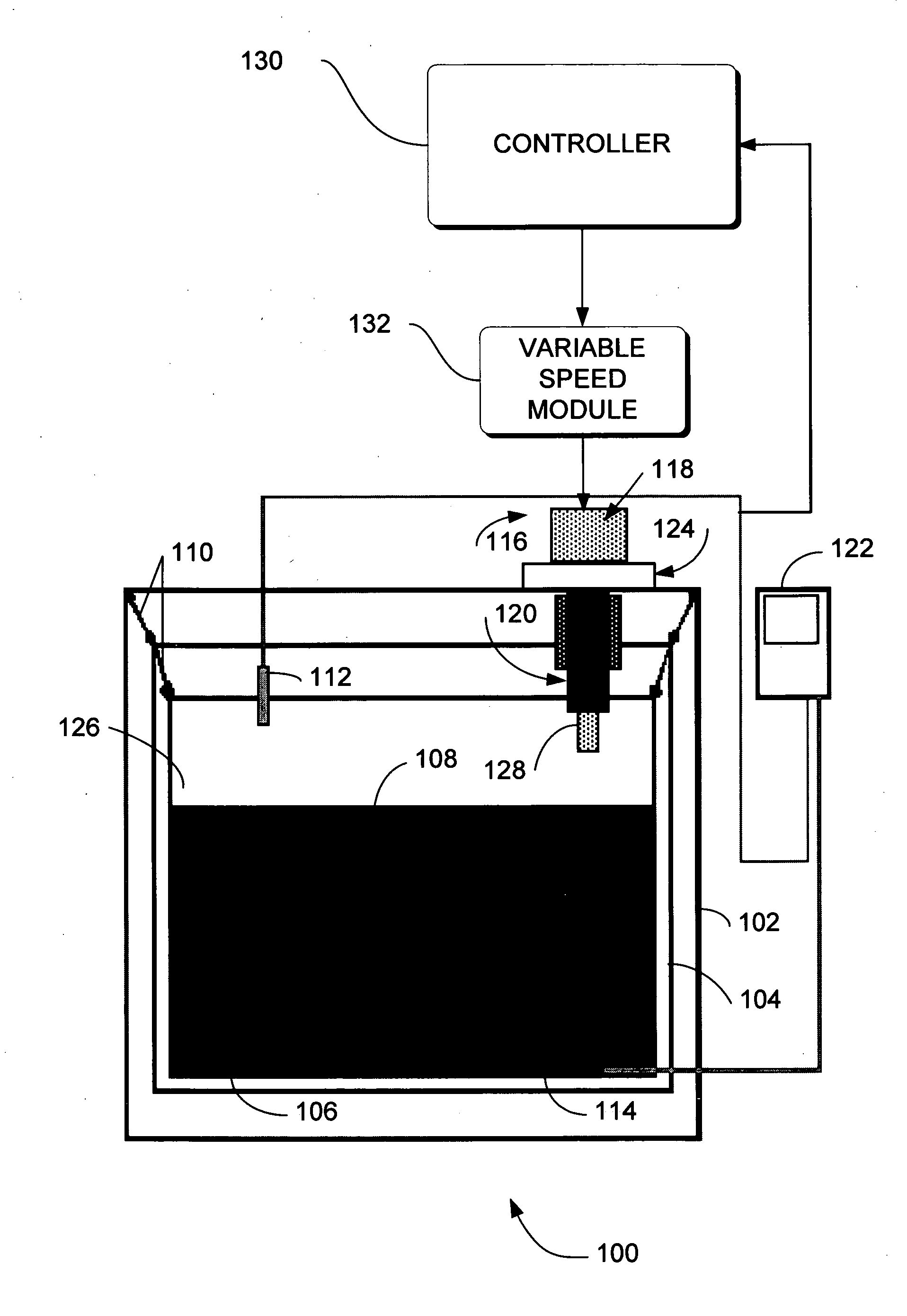
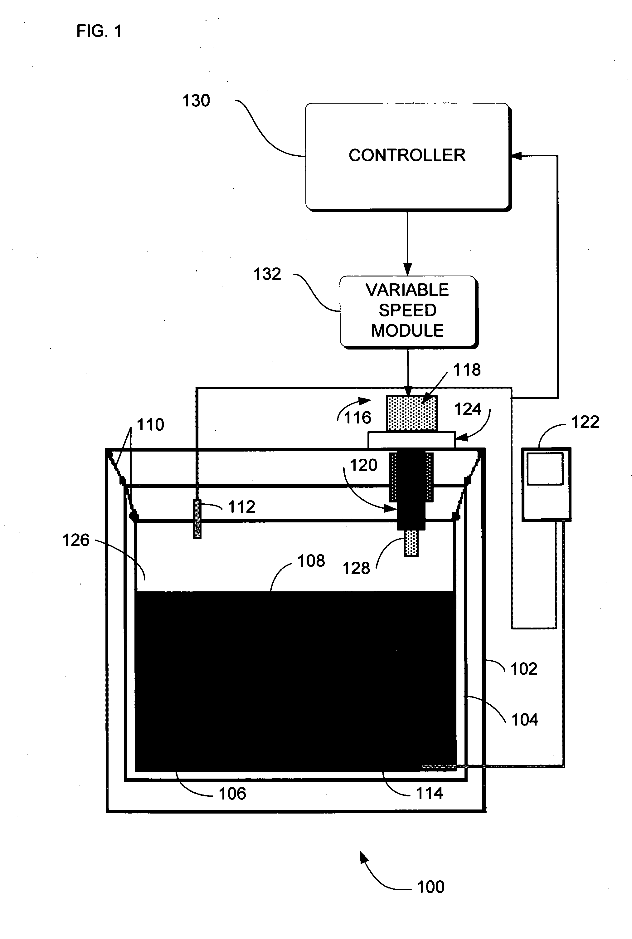
[0046] In the previous section, apparatus of the operation of an embodiment was described. In this section, the particular methods performed by controller 130 or computer 402 of such an embodiment are described by reference to a series of flowcharts.

[0047]FIG. 5 is a flowchart of a method 500 according to an embodiment. Method 500 solves the need in the art for a variable cooling capacity cryocooler.

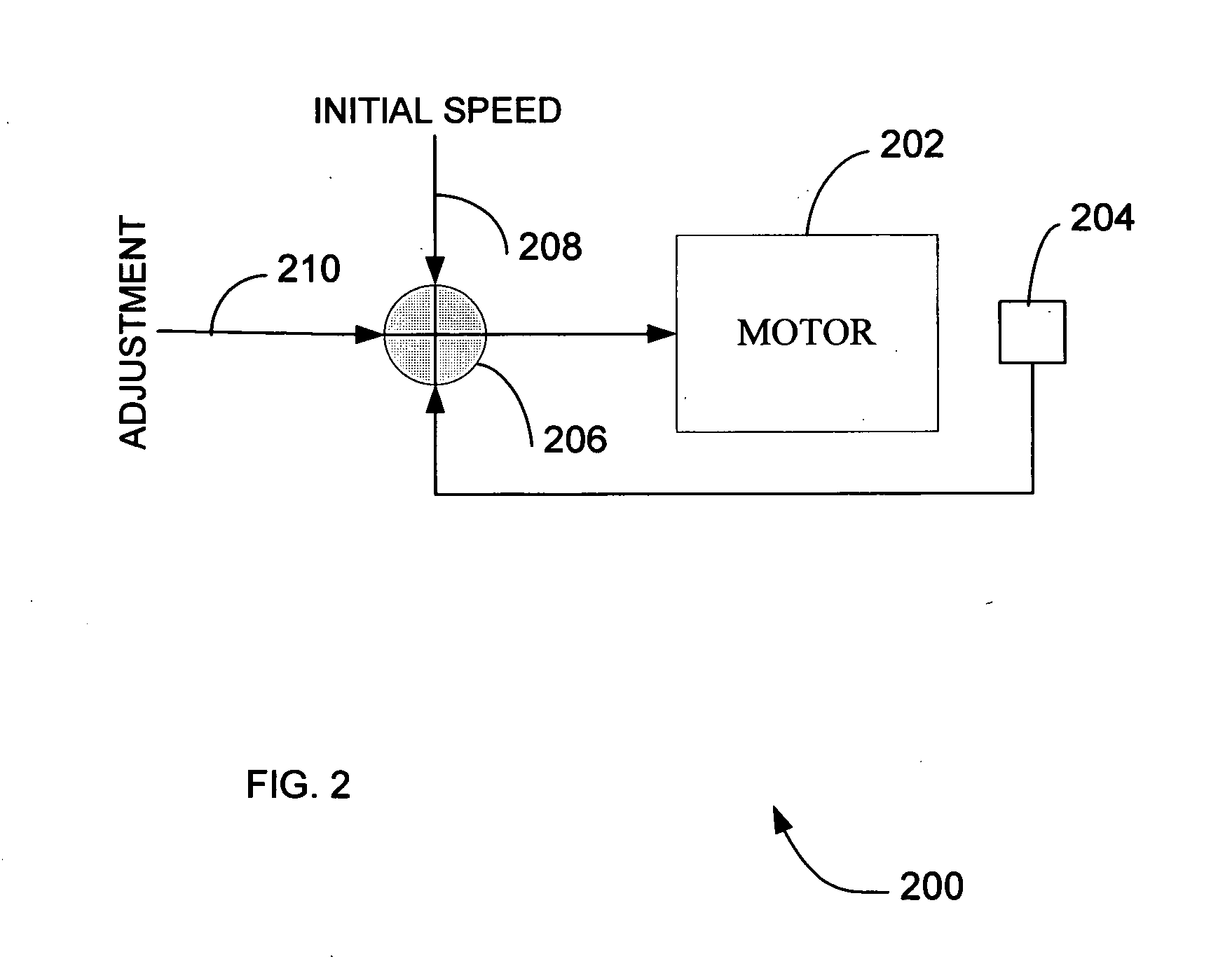
[0048] Method 500 begins with action 502. In action 502 an initial stroke rate or frequency is set for the electric power drive that drives the cryocooler displacer / piston that in turn determines the cooling capacity of the cryocooler. As noted earlier, conventional cryocoolers are set at a stroke frequency that maximizes the cooling capacity of the cryocooler. This maximum stroke rate reduces the life expectancy of moving components such as seals and component with dynamic contact surfaces in the cryocooler. The initial stroke frequency can be set to an arbitra...


PUM


Abstract

Systems and methods are provided for a variable cooling capacity cryocooler for a superconducting magnetic resonance imaging device having a liquid cryogen pressure vessel to provide cryogenic temperatures to a magnet assembly, a vacuum vessel surrounding the pressure vessel and a radiation shield spaced from the cryogen pressure vessel, and a pressure sensor positioned inside the cryogen pressure vessel pressure boundary for sensing pressure variations. A controller for varying the heat removal rate of the cryocooler based on the pressure variations in the cryogen pressure vessel and where the cooling capacity of the cryocooler is adjusted by modifying the speed of the electric power drive (DC or AC motors) or by changing the mechanical transmission ratio between the constant speed electric power drive and the cryocooler displacer/piston to adjust the cooler oscillating frequency of the gas flow. The invention can be adapted to magnets or non magnets systems using Stirling, Gifford-McMahon (“GM”) and Pulse Tube (“PT”) cooler systems. The system will extend component end of life and provide a controllable constant pressure improving image quality for superconducting MRI magnets.

Description

FIELD OF THE INVENTION [0001] This invention relates generally to a controller adapted to be used in a Stirling, Gifford-McMahon (“GM”) and Pulse Tube (“PT”) cooler systems, and more particularly to a controller for controlling the cooler oscillating frequency of the gas flow (thru cooler piston / displacer stroke frequency for Stirling and “GM”), applied to a zero boil-off superconducting magnet assembly. BACKGROUND OF THE INVENTION [0002] In conventional systems, a superconducting magnet becomes superconductive when placed in an extremely cold environment, such as by enclosing the magnet in a cryostat or pressure vessel and surrounding the magnet with a liquid cryogen such as liquid helium for cooling. [0003] The zero boil-off 4.2K magnet cooling system briefly consists of vacuum insulated liquid helium reservoir integrated into a cryostat with a radiation shield with temperature having a range of 40K to 70K and a liquid helium recondencing system in which saturated helium gas is re...

Claims


Application Information

Patent Timeline
IPC IPC(8): F25B9/00F25B49/00
CPCF25B9/10F25B9/14F25B9/145F25B2309/1411F25B2309/1428G05D23/1919F25D19/00F25D19/006F25D29/00F25D2400/02F25B2400/17G05D13/62H01F6/04H01F7/06
Inventor LEGALL, EDWIN L.DERAKHSHAN, MARKJIANG, LONGZHIMANGANO, ROY A.
Owner GENERAL ELECTRIC CO
Why Eureka
Try Eureka