Evaporator refrigeration system vehicle equipped with said system and method of evaporating refrigerant

a refrigeration system and evaporator technology, applied in indirect heat exchangers, lighting and heating apparatuses, transportation and packaging, etc., can solve the problems of deteriorating heat exchange performance, extremely low heat exchange efficiency, and extremely reduced heat exchange efficiency, so as to improve heat exchange efficiency

Inactive Publication Date: 2006-12-28
SHOWA DENKO KK
View PDF0 Cites 9 Cited by
  • Summary
  • Abstract
  • Description
  • Claims
  • Application Information

AI Technical Summary

Benefits of technology

[0072] In the invention, in cases where the structure as recited in the aforementioned Item 12 is employed, the gas phase refrigeran

Problems solved by technology

To the contrary, in the case in which vapor quality of refrigerant is higher than a predetermined value (a range of 0.4 to 0.6), the coefficient of evaporation heat transfer becomes extremely low, resulting in extremely decreased heat exchanging

Method used


Image

  • Evaporator refrigeration system vehicle equipped with said system and method of evaporating refrigerant
  • Evaporator refrigeration system vehicle equipped with said system and method of evaporating refrigerant
  • Evaporator refrigeration system vehicle equipped with said system and method of evaporating refrigerant

Examples


Embodiment Construction

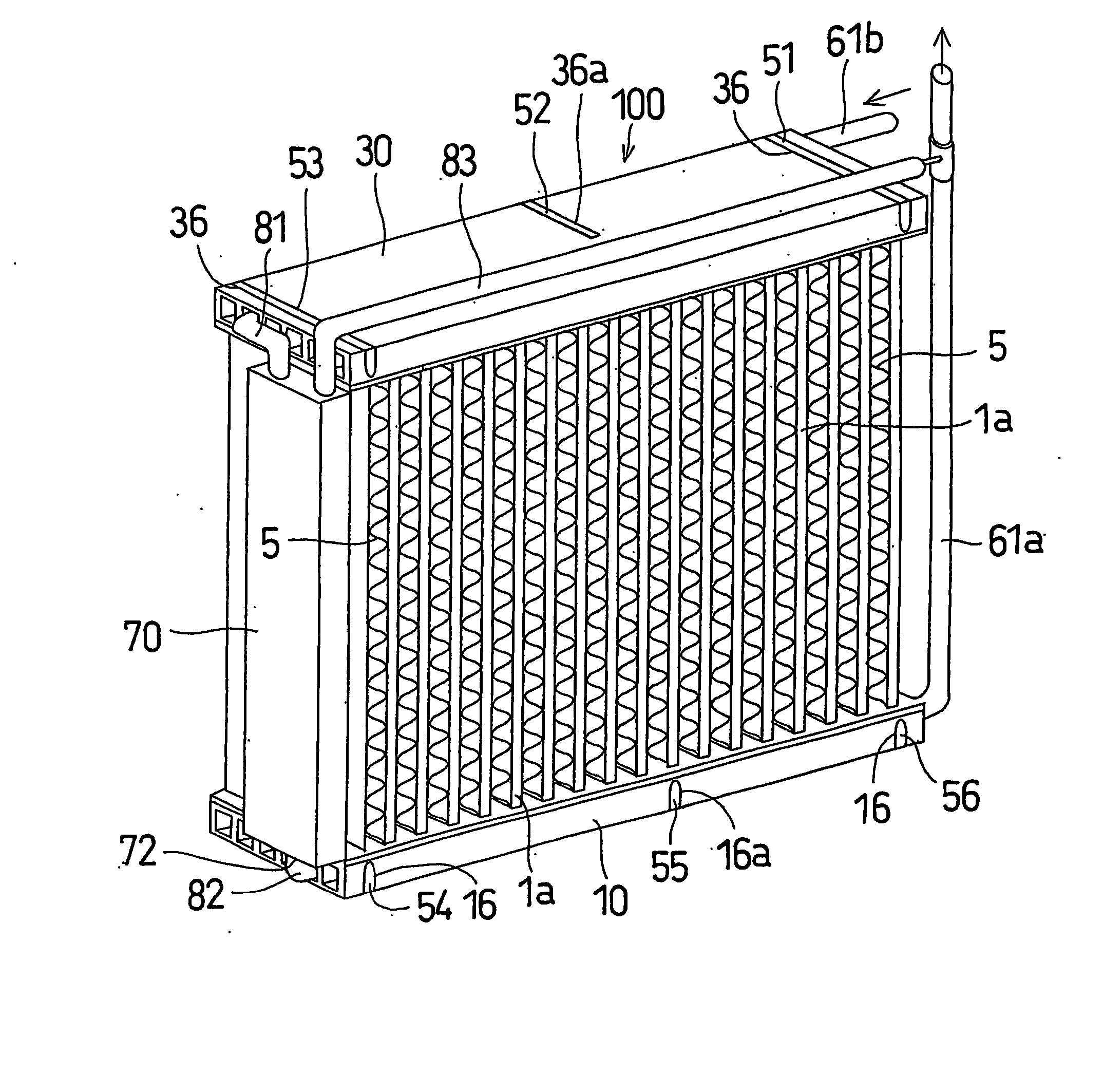
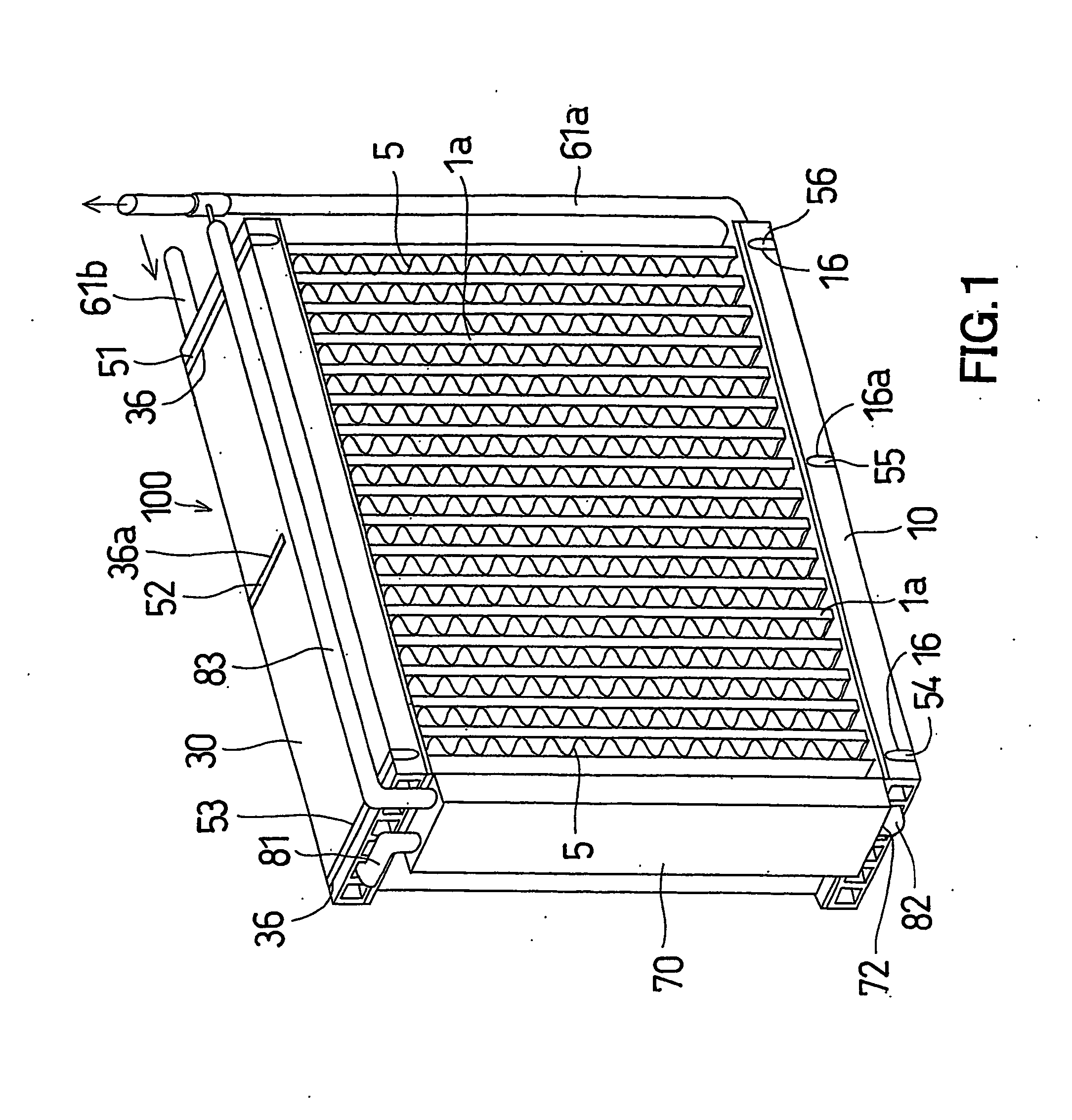
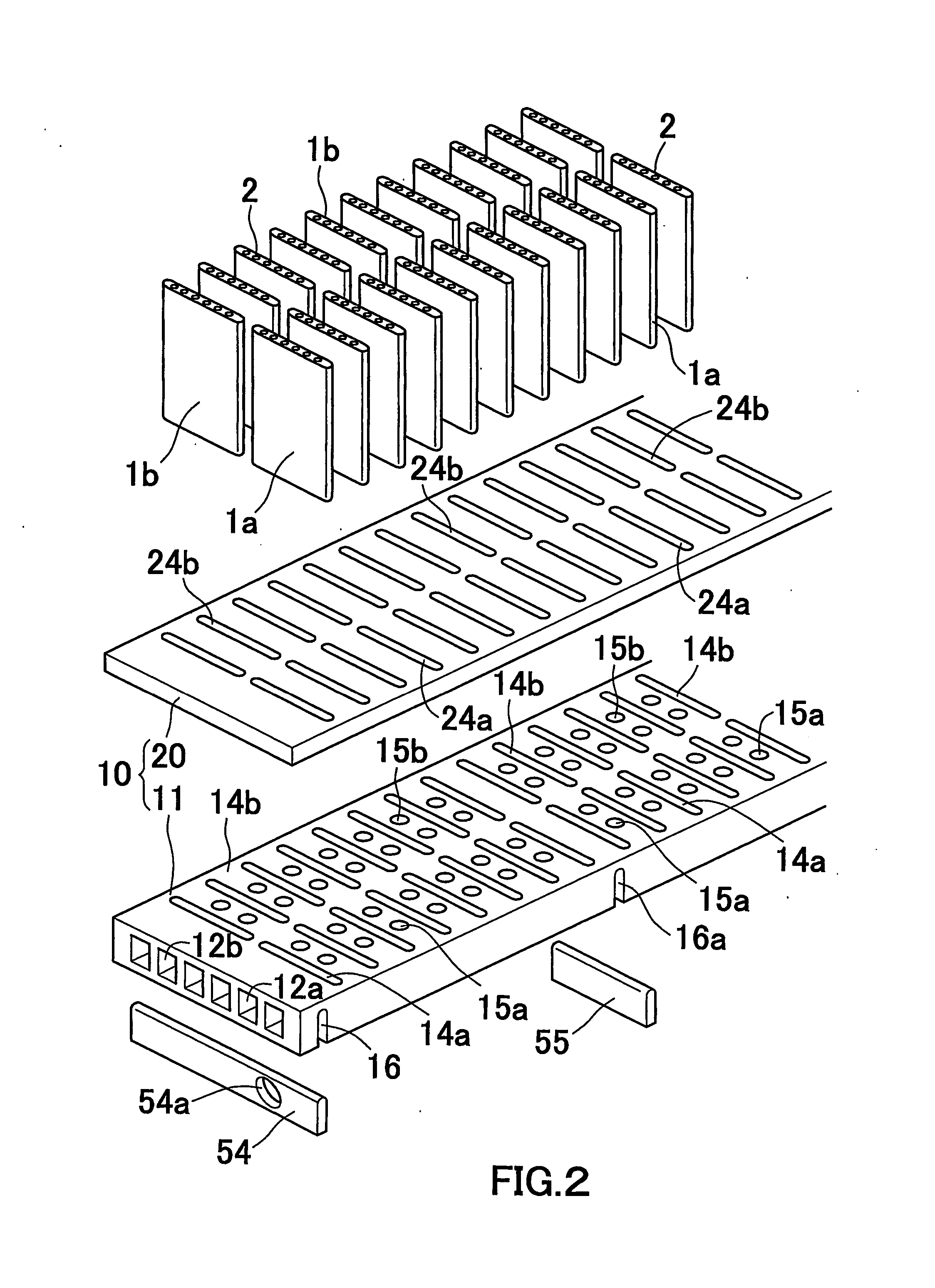
[0273] FIGS. 1 to 5 show an evaporation apparatus to be applied to a refrigeration system for use in vehicles which is an embodiment of the present invention. As shown in these figures, this evaporation apparatus is an apparatus to be applied to an vapor compressing type refrigeration cycle using CO2 as a refrigerant, and includes an evaporator 100 and a gas-liquid separator 70 provided at a part of a refrigerant passage of the evaporator 100.

[0274] The evaporator 100 is provided with, as fundamental structural components, a pair of upper and lower flat header tanks 10 and 30, flat heat exchanging tubes 1a and 1 b disposed between the pair of header tanks 10 and 30 with both ends thereof connected to the pair of header tanks 10 and 30 in fluid communication, arranged in parallel with each other in the longitudinal direction (right and left direction) of the header tank, and arranged in two rows in the widthwise direction (fore and aft direction) of the header tank, and corrugated f...


PUM


Abstract

An evaporator using a CO2 refrigeration that prevents a raise in vapor quality of refrigeration in an evaporator passage to obtain heat exchanging efficiency. The evaporator for use in a refrigeration system includes a refrigerant inlet for introducing a refrigerant, a refrigerant outlet for discharging the refrigerant, and an evaporator passage for causing the refrigerant introduced via the refrigerant inlet to evaporate and leading the refrigerant to the refrigerant outlet. An intermediate outlet is provided at an intermediate portion of the evaporator passage. A refrigerant high in vapor quality among the refrigerant passing through the intermediate portion from the refrigerant inlet flows out of the intermediate outlet to prevent a raise in vapor quality of refrigerant.

Description

CROSS REFERENCE TO RELATED APPLICATIONS [0001] This application is an application filed under 35 U.S.C. § 111(a) claiming the benefit pursuant to 35 U.S.C. § 119(e)(1) of the filing date of Provisional Application No. 60 / 478,303 filed on Jun. 16, 2003 pursuant to 35 U.S.C. § 111(b). [0002] Priority is claimed to Japanese Patent Application No. 2003-132044 filed on May 9, 2003, and U.S. Provisional Application No. 60 / 478,303 filed on Jun. 16, 2003, the disclosure of which are incorporated by reference in their entireties.TECHNICAL FIELD [0003] The present invention relates to a refrigeration system for use in a refrigeration cycle or the like using CO2 as a refrigerant. It also relates to an evaporator to be preferably used in the refrigeration system, a method of evaporating a refrigerant, and a vehicle equipped with the refrigeration system. BACKGROUND ART [0004] In a conventional vapor compression type refrigeration cycle, Freon series refrigerants are commonly used. In recent yea...

Claims


Application Information

Patent Timeline
IPC IPC(8): F28F7/00F25B43/00F25B39/02B60H1/32B60H1/00F25B1/00F25B9/00F28D1/053F28F9/02F28F27/02
CPCB60H1/00335F25B9/008F25B39/02F25B2309/06F25B2309/061F28F9/0278F28D2021/0085F28F9/0202F28F9/0204F28F9/0209F28F9/0221F28D1/05391
Inventor SHINMURA, ETSUOHANEDA, OSAMUTAKE, KOICHIRO
Owner SHOWA DENKO KK
Why Eureka
Try Eureka