

System and methodology for image and overlaid annotation display, management and communicaiton
a technology of image overlay and management, applied in the field of music, can solve the problems of complex and costly adaptations or variations of musical arrangements, remote musicians are unable to effectively practice together, and few musicians are limited
- Summary
- Abstract
- Description
- Claims
- Application Information
AI Technical Summary
Benefits of technology
Problems solved by technology
Method used
Image

Examples
Embodiment Construction
[0044] While this invention is susceptible of embodiment in many different forms, there is shown in the drawing, and will be described herein in detail, specific embodiments thereof with the understanding that the present disclosure is to be considered as an exemplification of the principles of the invention and is not intended to limit the invention to the specific embodiments illustrated.
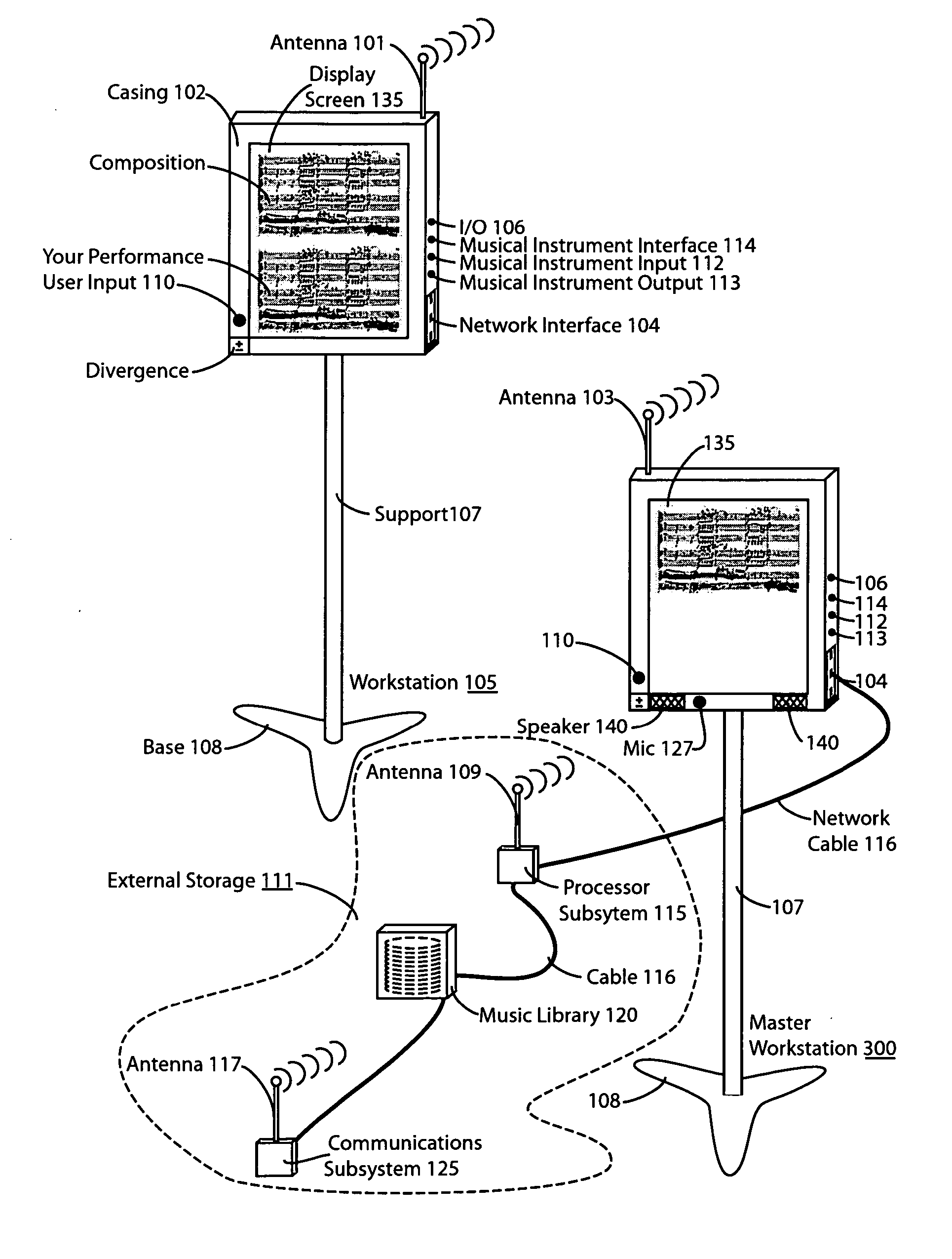
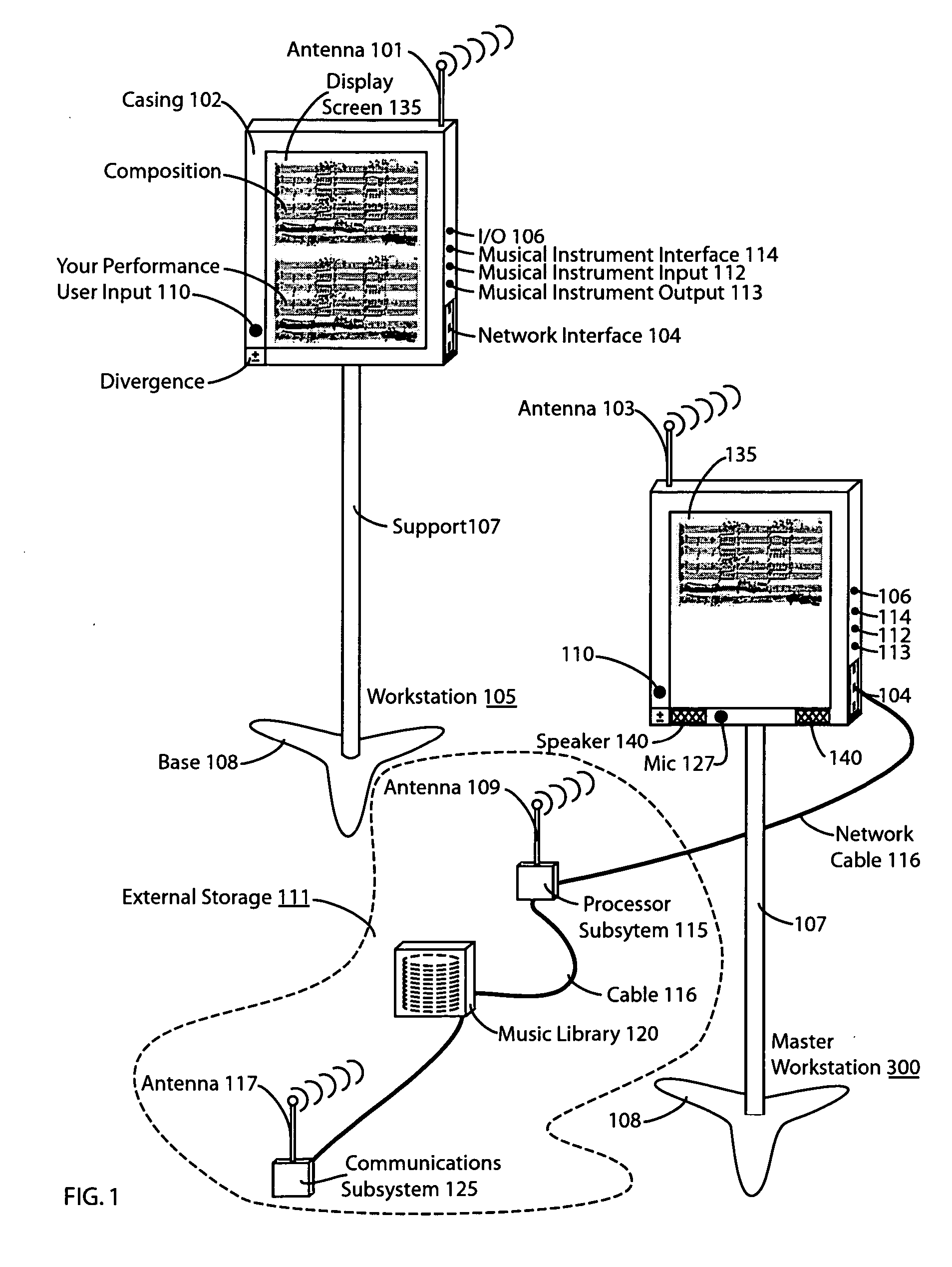
[0045] As illustrated in FIG. 1, a system controller, in the form of a music stand (105) with a liquid crystal display, is used by an operator (e.g., performer, conductor, etc.) to select one or more musical compositions. FIG. 1 illustrates two types of music workstations stands. The workstation stand (105) provides certain optional features for a more full-featured stand, including as illustrated, speakers (140) both wireless and wired communications capability, and as illustrated, shows a processor subsystem with memory (115) as an external separate component. The master music stand (300) shows...
PUM
 Abstract
Description
Claims
Application Information