
Modular radiant heating apparatus

a technology of radiant heating and modules, applied in the field of radiant heating apparatuses, can solve the problems of inconvenient use, inconvenient maintenance, and inability to meet the needs of users, and achieve the effects of the existing apparatus, and improving the efficiency of the existing method

Active Publication Date: 2006-12-28
GREENHEAT IP HLDG LLC
View PDF99 Cites 47 Cited by
  • Summary
  • Abstract
  • Description
  • Claims
  • Application Information

AI Technical Summary

Benefits of technology

[0025] In one embodiment, the top and bottom pliable outer layers are joined to enclose the pliable planar heat spreading layer and the thermal isolation layer. The top and bottom pliable outer layers provide durable protection in an outdoor environment.

Problems solved by technology

Cold, ice, snow, and frost are undesirable in many fields.
Such methods are often expensive, time consuming, inefficient, and otherwise problematic.
Additionally, many situations exist in which a volume of space needs to be heated but existing methods and apparatuses for doing so are problematic.
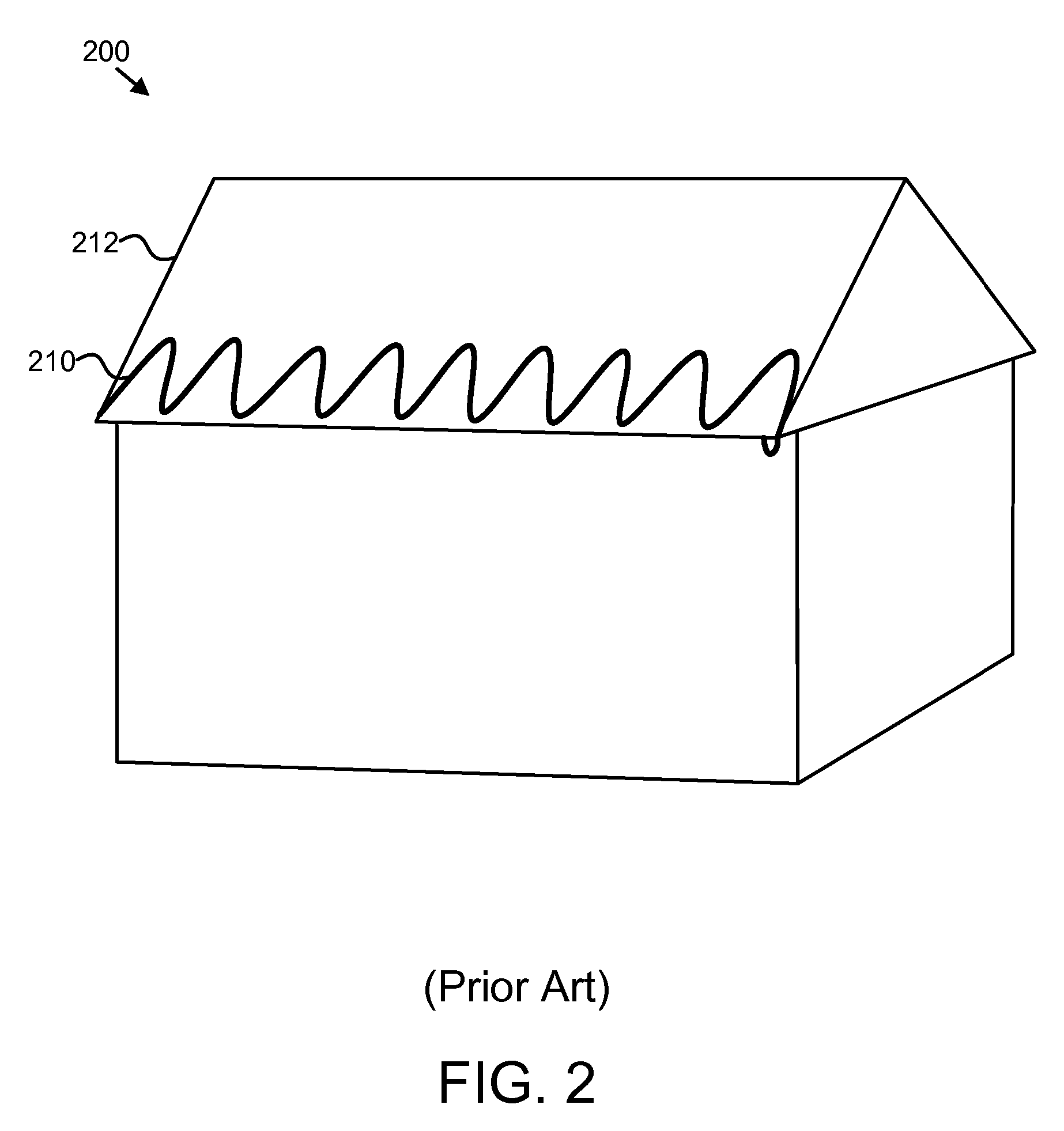
For example, normal ways of heating a residence include forced-air systems or radiant heat systems using heated water or oil that flows through pipes through the walls, floors, or a heating register of a room, with commensurate complications of dryness, moisture, water pipe breakage, and other problems.
Currently, few conventional solutions exist that use electricity to produce and conduct heat.
Traditionally, this was due to limited circuit designs, and inefficient management of the electrically produced heat.
Traditional solutions were unable to produce sufficient heat over a sufficient surface area to be practical.
These higher voltages and currents are often unavailable at either residential or commercial sites.
Thus, using conventional standard circuits, conventional solutions are unable to produce sufficient heat over a sufficiently large surface area to be practical.
In addition, specialized electrical circuits for the higher voltages increased the costs of installing such systems and the energy bills for operating the systems.

Method used


Image

  • Modular radiant heating apparatus
  • Modular radiant heating apparatus
  • Modular radiant heating apparatus

Examples


Embodiment Construction

[0048] Reference throughout this specification to “one embodiment,”“an embodiment,” or similar language means that a particular feature, structure, or characteristic described in connection with the embodiment is included in at least one embodiment of the present invention. Thus, appearances of the phrases “in one embodiment,”“in an embodiment,” and similar language throughout this specification may, but do not necessarily, all refer to the same embodiment.

[0049] Furthermore, the described features, structures, or characteristics of the invention may be combined in any suitable manner in one or more embodiments. In the following description, numerous specific details are provided to provide a thorough understanding of embodiments of the invention. One skilled in the relevant art will recognize, however, that the invention may be practiced without one or more of the specific details, or with other methods, components, materials, and so forth. In other instances, well-known structure...


PUM


Abstract

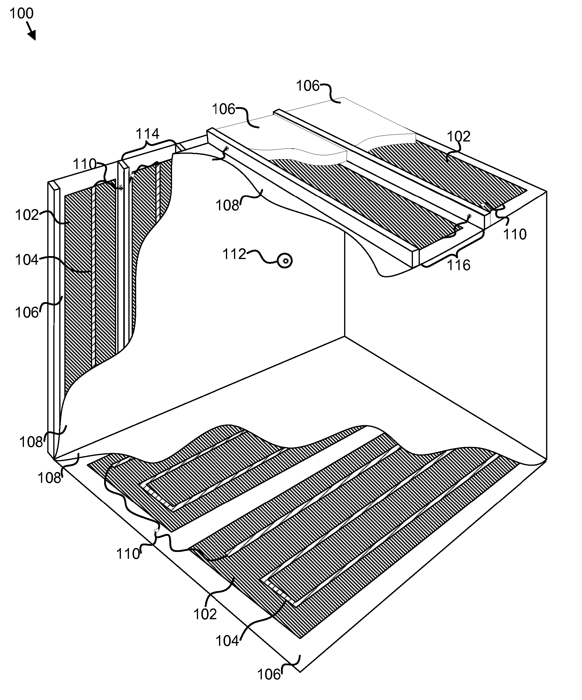
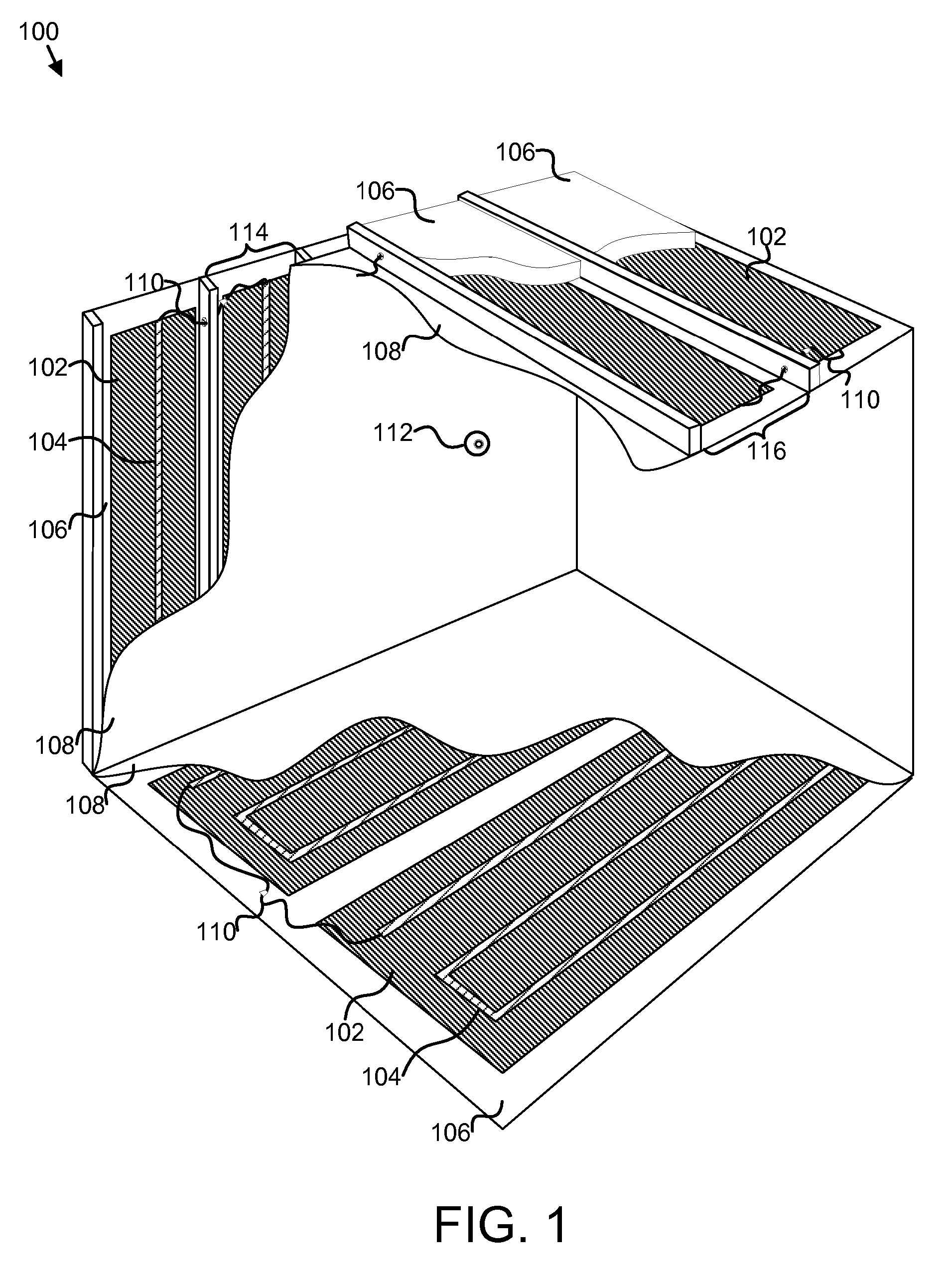
The radiant heating apparatus is disclosed, having a planar electrical heating element, a planar heat spreading layer, a finishing layer, a thermal isolation layer, and an electric power coupling. The planar electrical heating element converts electrical energy to heat energy. The planar heat spreading layer is in contact with the planar electrical heating element, and draws the heat energy out of the planar electrical heating element and distributes the heat energy. The finishing layer is disposed to one side of the planar heat spreading layer. The thermal isolation layer is disposed to an opposite side of the planar heat spreading layer as the finishing layer. Heat from the planar heat spreading layer conducts away from the thermal isolation layer and toward the finishing layer. The electric power coupling is connected to the electrical heating element to supply electrical power.

Description

CROSS-REFERENCES TO RELATED APPLICATIONS [0001] This application claims the benefit of U.S. Provisional Patent Application No. 60 / 688,146 entitled “LAMINATE HEATING APPARATUS” and filed on Jun. 6, 2005 for David Naylor which is incorporated herein by reference. This application also incorporates by reference and claims priority to Utility patent application Ser. No. 11 / 218,156 entitled “MODULAR HEATED COVER” and filed on Sep. 1, 2005 for David Naylor, Utility patent application Ser. No. 11 / 344,830 entitled “MODULAR HEATED COVER” and filed on Feb. 1, 2006 for David Naylor and Dan Alex Hillesheim. This application also incorporates by reference and claims priority to U.S. Provisional Patent Application No. 60 / 654,702 entitled “A MODULAR ACTIVELY HEATED THERMAL COVER” and filed on Feb. 17, 2005 for David Naylor through pending Utility patent application Ser. No. 11 / 218,156 entitled “MODULAR HEATED COVER” listed above, and to U.S. Provisional Patent Application No. 60 / 656,060 entitled “...

Claims


Application Information

Patent Timeline
IPC IPC(8): F24C5/04
CPCE04D13/103F24C7/062F24C7/043
Inventor NAYLOR, DAVID
Owner GREENHEAT IP HLDG LLC
Learn More