
Machine element part with ic tag

Inactive Publication Date: 2006-12-28
NTN CORP
View PDF8 Cites 18 Cited by
  • Summary
  • Abstract
  • Description
  • Claims
  • Application Information

AI Technical Summary

Benefits of technology

[0009] An object of the present invention is therefore to provide a machine component with an IC tag affixed thereto, in which with the IC tag having an increased storage capacity, the IC tag can be mounted with no difficulty and, also, reading or writing of information from or in the IC tag, respectively, can be facilitated.
[0010] Another object of the present invention is to substantially eliminate the possibility of the unbalanced revolution, which may occur when the IC tag is mounted on a rotatable component part of the machine component.
[0011] A further object of the present invention is to enable contents of the handling manual to be presented easily and, also, to enable the handling manual to be retained semipermanently in a discernable form.

Problems solved by technology

Although the foregoing problems have been discussed as being found where the machine component is a bearing assembly, problems similar to those discussed above may be equally found with any other machine components such as, for example, shaft couplings and motors that tend to deteriorate naturally with passage of time of use.
When it comes to attachment of an IC tag to a machine component, not only is the site of placement limited, but the outside dimensions of the IC tag that can be attached to the machine component is limited.
However, if a small IC tag is used, the storage capacity thereof is indeed small and it may occur that a sufficient amount of information cannot be stored in it.
The use of a large IC tag to increase the storage capacity will result in such problems and inconveniences that part of the IC tag may protrude outwardly to form an obstacle to the neighboring parts and that the presence of a hole or recess for accommodating the IC tag may decrease the strength of the machine component.
Where the IC tag is attached to the machine component, it is desirable to mount the IC tag on a portion of the machine component or its peripheral part that does not affect the strength and the precision, but where that portion of the machine component or its peripheral part is a rotatable element such as, for example, a roller retainer or cage employed in a rolling bearing assembly, mounting of the IC tag will eventually lead to disruption of a balance of the mass, accompanied by reduction in performance of the machine component.
Also, with the handling manual of the kind having the display module for presenting the status of deterioration as discussed above, it can serve the expected purpose if and so long as the machine or equipment is used within an agreeable environment such as, for example, an indoor space, but where the machine or equipment is used in the outdoor space, the handling manual may be susceptible to contamination and / or breakage that lead to the incapability of reading the part model number and the specification.
By way of example, the iron and steel manufacturing equipment is generally full of powder dust, metallic powder (scale) and / or pulp chaff and railway vehicles are susceptible to contamination brought about by rain and powder dust, and it is therefore quite often that the part model number and the specification both referred to above will be hard to make out or incapable of being deciphered quickly.
Yet, in the conventional art, when it comes to attachment of the IC tag to a packaging container or the like of the machine component, the IC tag is so small as to pose a problem associated with handling thereof and, therefore, not only is the attachment complicated and time-consuming, but also the IC tag is hard to be reused.

Method used


Image

  • Machine element part with ic tag
  • Machine element part with ic tag
  • Machine element part with ic tag

Examples


Embodiment Construction

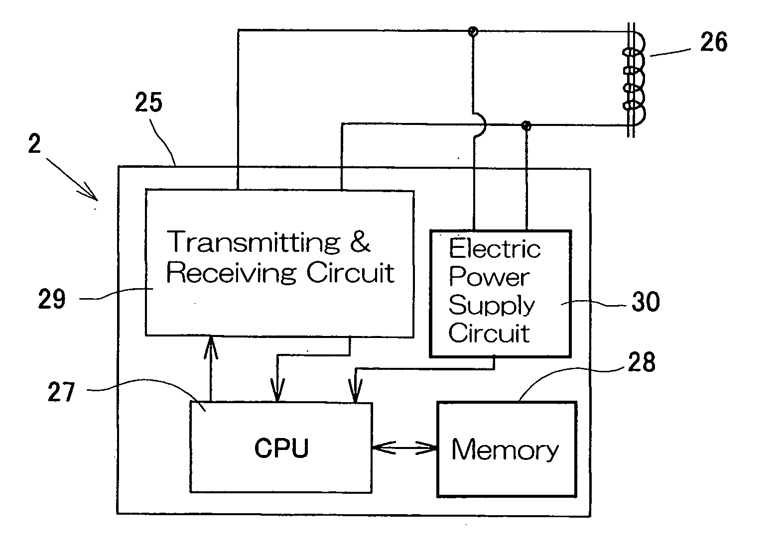
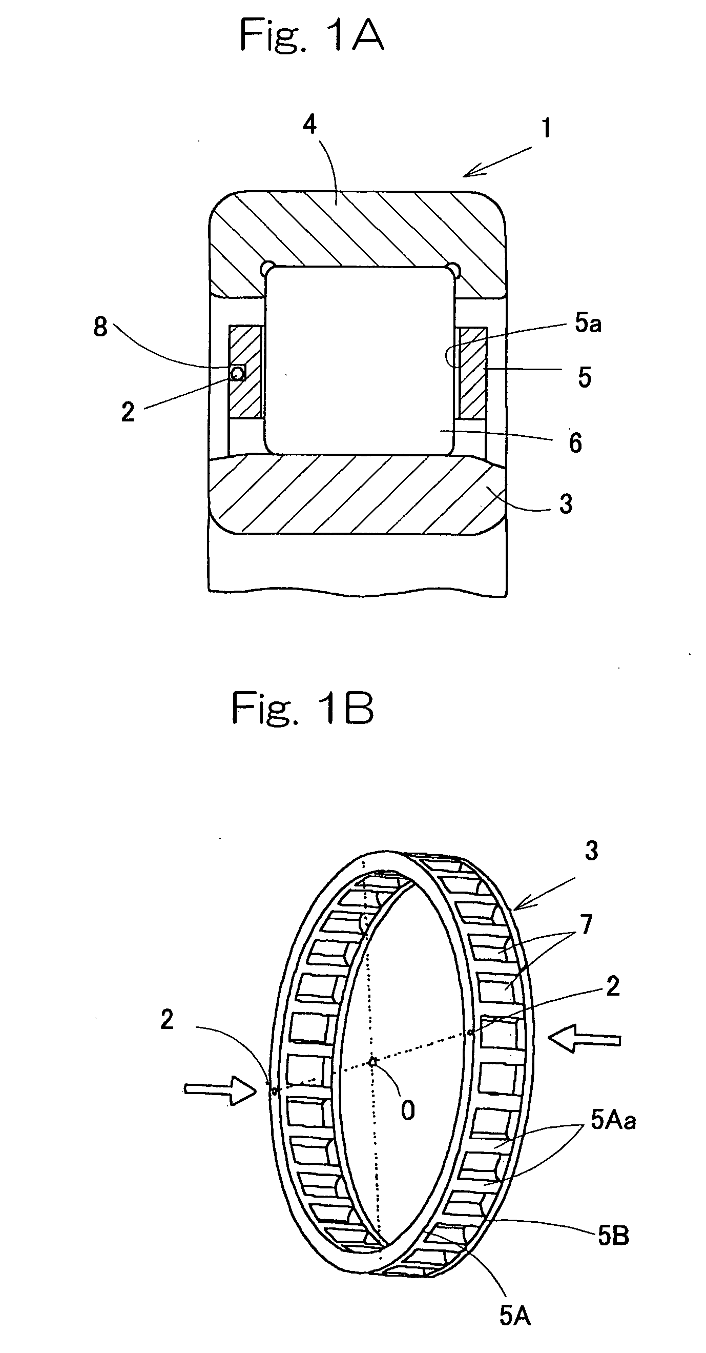
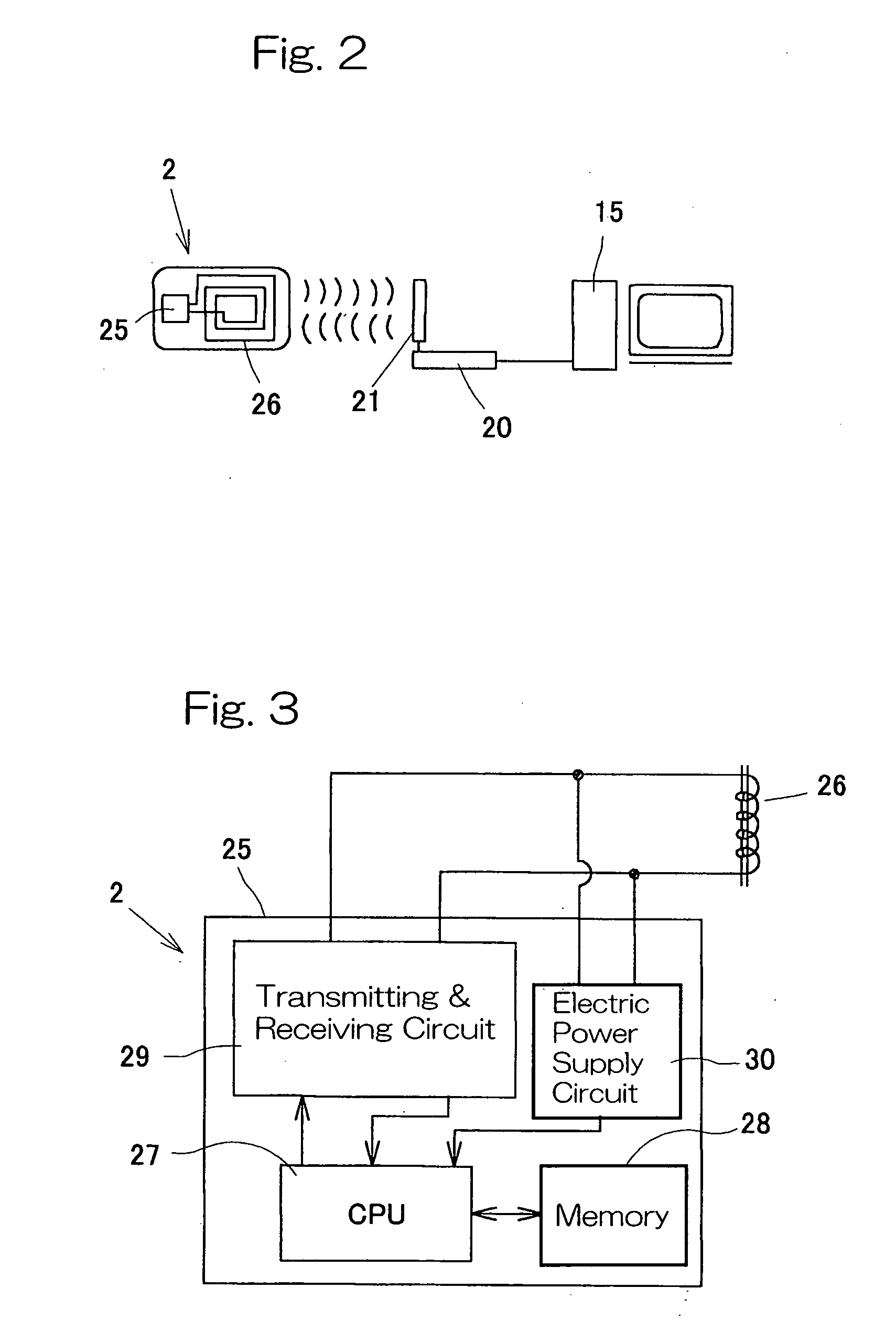
[0056] A first preferred embodiment of the present invention will be described in detail with particular reference to FIGS. 1A to 3. The IC tag-equipped machine component shown therein is in the form of a rolling bearing assembly 1, which forms a machine component, having a plurality of IC tags 2 attached thereto. The rolling bearing assembly 1 is of a type including a row of rolling elements 6 retained by a roller retainer 5 and interposed between an inner race 3 and an outer race 4. No sealing member is employed and the roller retainer 5 is exposed to the outside through opposite annular open ends of the rolling bearing assembly 1. Although the rolling bearing assembly 1 may be a cylindrical roller bearing, a tapered roller bearing, a deep groove ball bearing or an angular contact ball bearing, the cylindrical roller bearing is employed in the illustrated embodiment as an example of the rolling bearing assembly 1. Also, although the inner race 3 is shown as a collarless type and t...


PUM


Abstract

To provide a machine component with an IC tag affixed thereto, in which with the IC tag having an increased storage capacity, the IC tag can be mounted with no difficulty and, also, reading or writing of information from or in the IC tag, respectively, can be facilitated. A plurality of IC tags 2 are attached to a machine component, which forms a part of a rolling bearing assembly 1, or to a machine component and an accessory with division made therebetween. Those plural IC tags 2 have different information stored therein. Where the machine component is a retainer incorporated rolling bearing assembly 1, those plural IC tags are attached to a roller retainer 5 at respective locations symmetrical with each other about the axis O of rotation thereof.

Description

FIELD OF THE INVENTION [0001] The present invention relates to a machine component having an IC tag attached thereto such as, for example, a rolling bearing assembly having an IC tag attached to a component thereof or an accessory thereto. BACKGROUND ART [0002] It is generally well known that machine components such as, for example, bearing assemblies have significant pieces of information affixed thereto: Some of those pieces of information include part of the model numbers and are marked by stamping on an outer surface area of the machine component and some others recorded in documents that are separately replaced and stored. Those piece of information affixed to the machine components include, in the case of bearing assemblies, design information such as, for example, gap precision, material used to form each machine component, type of heat treatment used and description of grease filled, and / or management codes such as, for example, manufacturer's production number and customer'...

Claims


Application Information

Patent Timeline
IPC IPC(8): G06F17/00G06K19/00G05B19/418F16C33/46F16C33/78F16C33/80F16C41/00G05B19/12
CPCF16C19/26F16C33/38F16C33/4623G06Q10/087F16C41/008G05B19/12F16C33/78F16C19/52Y02P90/02
Inventor YAMAMOTO, NAOTAHORIUCHI, KENFUJIMOTO, KOUSHIROUSHIBUYA, YOSHIHISAMURAMATSU, MAKOTO
Owner NTN CORP
Learn More