Sensorless control systems and methods for permanent magnet rotating machines

a permanent magnet rotating machine and sensorless technology, applied in the direction of electronic commutators, dynamo-electric converter control, instruments, etc., can solve the problems of occupying space within the motor housing and the price of the rotor position sensor

Active Publication Date: 2006-12-28
COPELAND LP
View PDF4 Cites 68 Cited by
  • Summary
  • Abstract
  • Description
  • Claims
  • Application Information

AI Technical Summary

Problems solved by technology

However, rotor position sensors can be quite expensive, occupy space within a motor housing, and sometimes fail.

Method used


Image

  • Sensorless control systems and methods for permanent magnet rotating machines
  • Sensorless control systems and methods for permanent magnet rotating machines
  • Sensorless control systems and methods for permanent magnet rotating machines

Examples


Embodiment Construction

[0023] Illustrative embodiments of the invention are described below. In the interest of clarity, not all features of an actual implementation are described in this specification. It will be appreciated that in the development of any actual embodiment, numerous implementation-specific decisions must be made to achieve specific goals, such as performance objectives and compliance with system-related, business-related and / or environmental constraints. Moreover, it will be appreciated that such development efforts may be complex and time-consuming, but would nevertheless be a routine undertaking for those of ordinary skill in the art having the benefit of this disclosure.

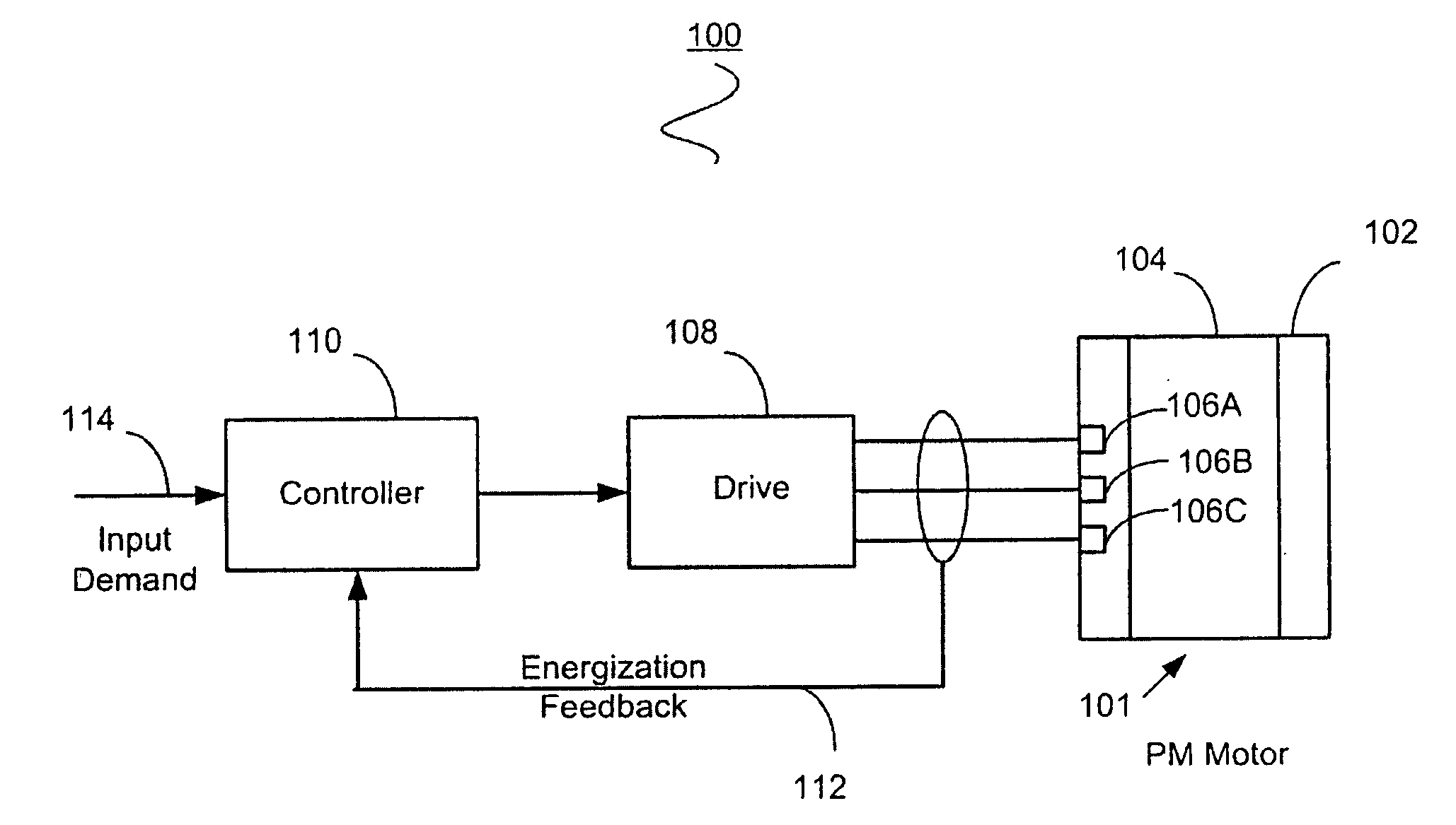
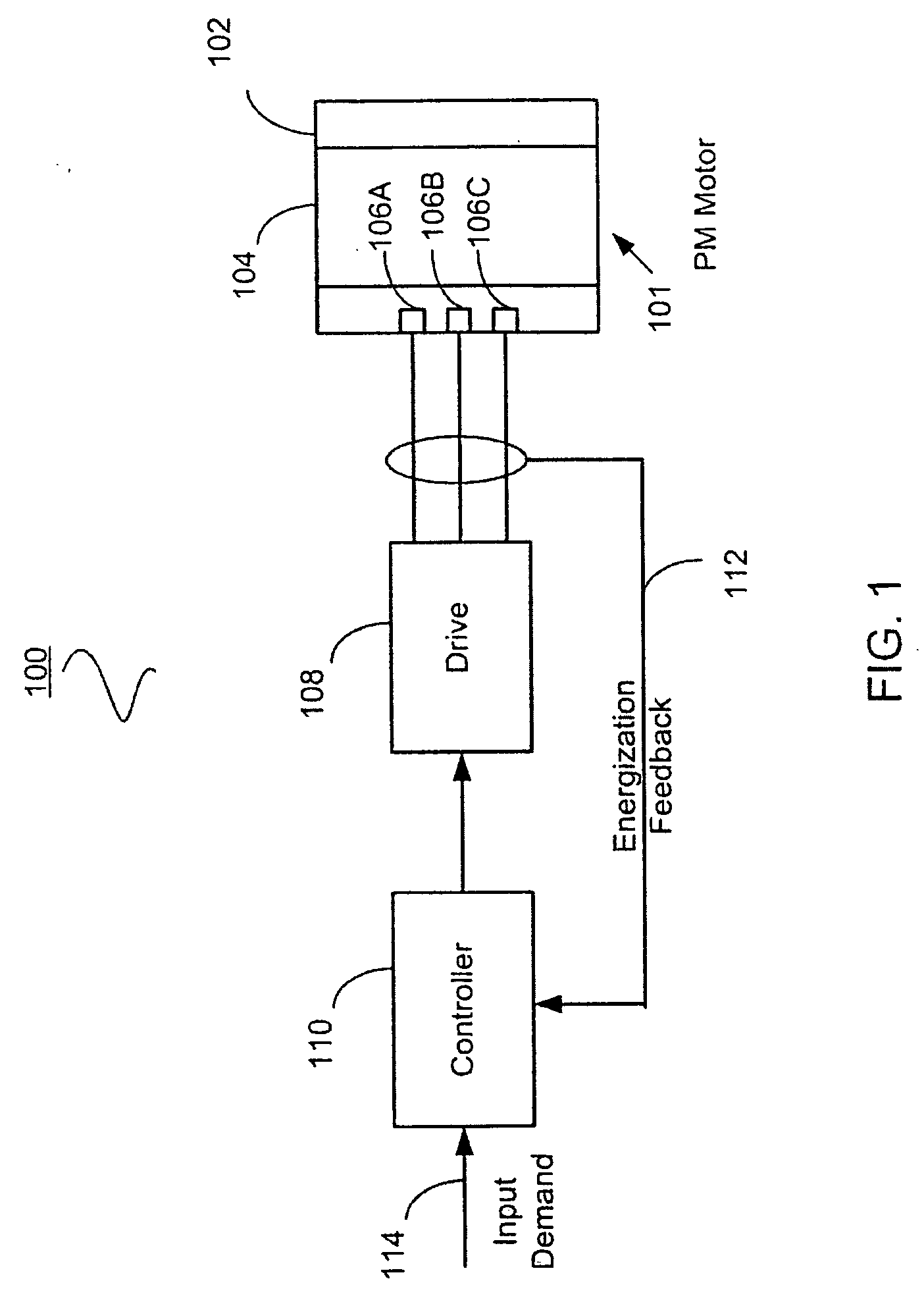
[0024]FIG. 1 illustrates a rotating permanent magnet machine system 100 according to one embodiment of the present invention. The machine system 100 includes a rotating permanent magnet electric machine 101, such as a permanent magnet alternating current (PMAC) motor or a hybrid permanent magnet / switched reluctance (P...


PUM


Abstract

Systems and methods for controlling a rotating electromagnetic machine. The rotating machine, such as a permanent magnet motor or hybrid switched reluctance motor, includes a stator having a plurality of phase windings and a rotor that rotates relative to the stator. A drive is connected to the phase windings for energizing the windings. A controller outputs a control signal to the drive in response to an input demand such as a demanded speed or torque. Control methods (which can be implemented separately or in combination) include varying the gain of an estimator as a function of a demanded or estimated speed to position control system poles at desired locations, decoupling control system currents to achieve a constant torque with motor speed, compensating flux estimates of the estimator for saturation operation of the stator, estimating rotor position using averages of sample values of energization feedback, and calculating a trim adjusted speed error from a plurality of speed estimates.

Description

CROSS-REFERENCE TO RELATED APPLICATIONS [0001] This application claims the benefit of U.S. Provisional Applications No. 60 / 694,077 and No. 60 / 694,066 filed Jun. 24, 2005, the entire disclosures of which are incorporated herein by reference.FIELD OF THE INVENTION [0002] The present invention relates generally to control of rotating machines, including but not limited to sensorless control of permanent magnet rotating machines. BACKGROUND OF THE INVENTION [0003] Permanent magnet machines, such as brushless permanent magnet motors, have been conventionally provided with position sensing devices. Such devices indicate, for use in controlling the motor, the rotor position with respect to the stator. However, rotor position sensors can be quite expensive, occupy space within a motor housing, and sometimes fail. To eliminate the need for position sensors, various “sensorless” motor constructions and methods have been developed with varying degrees of success. As recognized by the present i...

Claims


Application Information

Patent Timeline
Patent Type & Authority Applications(United States)
IPC IPC(8): H02P5/00
CPCH02P25/08H02P6/18
Inventor MARCINKIEWICZ, JOSEPH G.SHAHI, PRAKASH B.HENDERSON, MICHAEL I.
Owner COPELAND LP
Why Eureka
Try Eureka