
Three-dimensional image display apparatus

a display apparatus and three-dimensional technology, applied in the direction of electrical apparatus, holographic optical components, instruments, etc., can solve the problems of limiting the visibility of a human being approximately one minute, affecting the effect of the display density of the display apparatus in the present situation, and affecting the effect of the display density

Inactive Publication Date: 2006-12-28
SONY CORP
View PDF9 Cites 49 Cited by
  • Summary
  • Abstract
  • Description
  • Claims
  • Application Information

AI Technical Summary

Benefits of technology

[0011] Accordingly, it is an embodiment of the present invention to provide a three-dimensional image display apparatus which can produce and scatter a light ray group necessary for display of a three-dimensional image in a high spatial density to obtain a three-dimensional image formed from rays of light having quality proximate to that of an article in the real world without increase in scale of the three-dimensional image display apparatus.

Problems solved by technology

However, an image produced by the light ray reproduction method in the present situation lacks in the feeling of presence when compared with an article existing in the real world.
Generally, it is considered that the limit to visibility of a human being is approximately one minute in angular resolution, and a three-dimensional image by the light ray reproduction method in the present situation is formed from rays of light insufficient for the visual sense of a human being.
However, rapid enhancement of the display density in display apparatus in the present situation is difficult from the problem of the light utilization efficiency or the diffraction limit.
Further, in the case of the apparatus shown in FIG. 36, since there is a limitation to miniaturization of the projector units 701, it is considered difficult to array the projector units 701 in a high spatial density.
In any case, in order to produce a light ray group of a high density, a plurality of devices are required, and therefore, a large scale configuration of an entire apparatus cannot be avoided.

Method used


Image

  • Three-dimensional image display apparatus
  • Three-dimensional image display apparatus
  • Three-dimensional image display apparatus

Examples


first working example

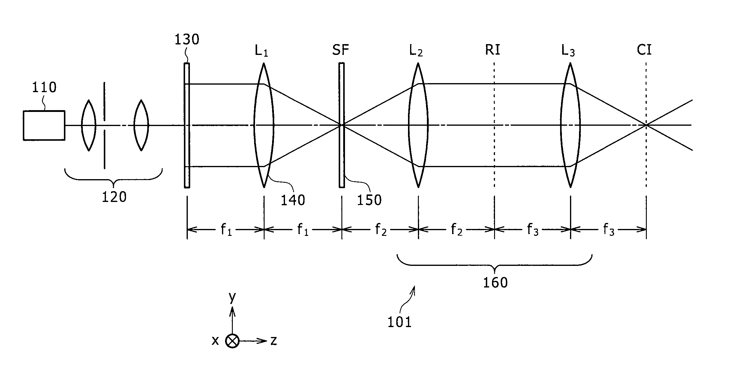
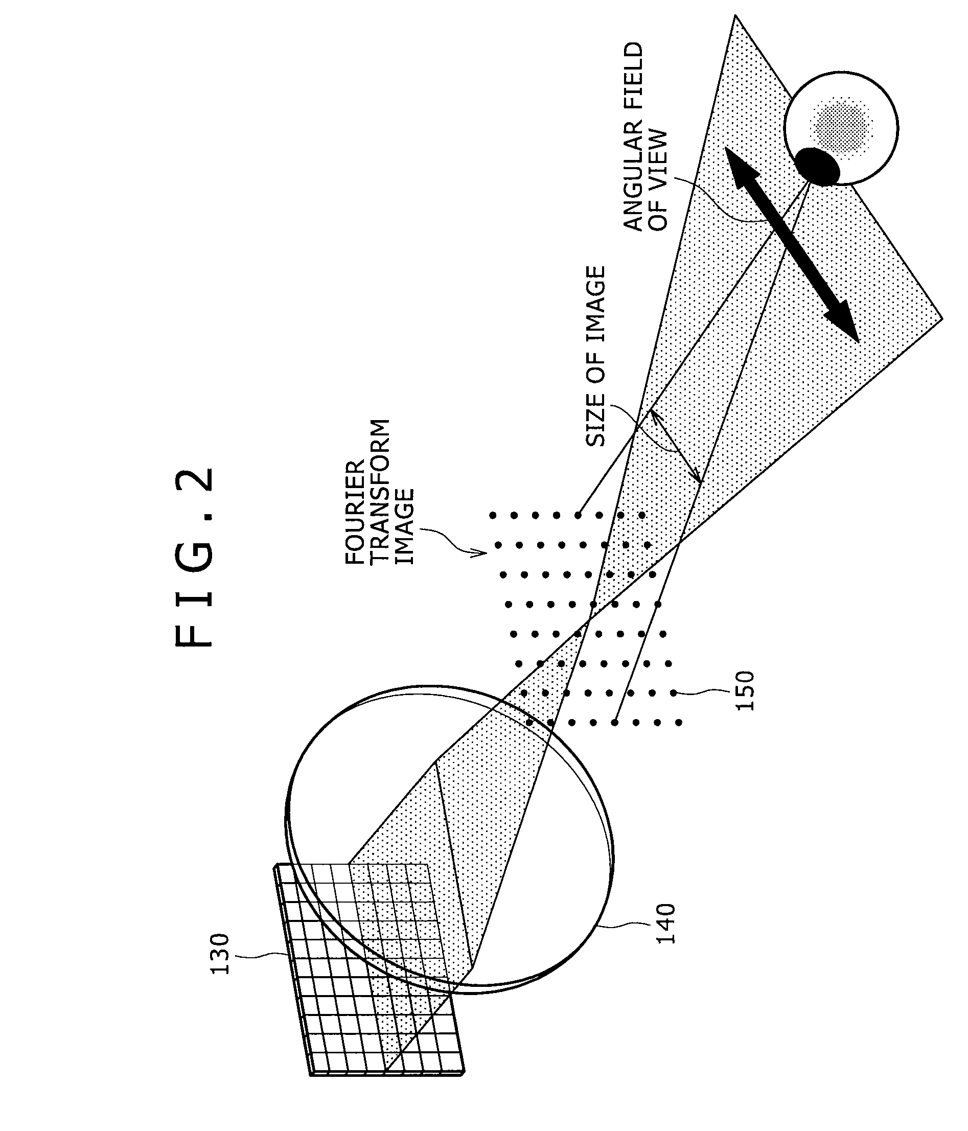
[0163] Referring first to FIGS. 1 to 3, there is shown a three-dimensional image display apparatus according to a first working example of the present invention which corresponds to the first and fourth embodiments of the present invention. The three-dimensional image display apparatus is formed as a three-dimensional image display apparatus of a single color display type. It is to be noted that, in the following description, an optical axis of the three-dimensional display apparatus is defined as a z axis while coordinate axes of a rectangular coordinate system in a plane perpendicular to the z axis are defined as an x axis and a y axis. Further, a direction parallel to the x axis is defined as an X direction, and a direction parallel to the y axis is defined as a Y direction. The X direction is, for example, a horizontal direction of the three-dimensional image display apparatus, and the Y direction is, for example, a vertical direction of the three-dimensional image display appar...

second working example

[0220] The second working example is a three-dimensional image display apparatus according to the second and fifth embodiments of the present invention. FIGS. 15, 16 and 17 illustrate a concept of the three-dimensional image display apparatus of the second working example. Also the three-dimensional image display apparatus of the second working example is formed as a three-dimensional image display apparatus of a single color display type. FIG. 15 illustrates a concept of the three-dimensional image display apparatus of the second working example along the yz plane. Also a conceptive view of the three-dimensional image display apparatus of the second working example along the xz plane is substantially similar to FIG. 15. Meanwhile, FIG. 16 illustrates a concept of the three-dimensional image display apparatus of the second working example when it is viewed in an oblique direction, and FIG. 17 schematically illustrates an arrangement state of components of the three-dimensional image...

third working example

[0277] The third working example is a three-dimensional image display apparatus according to the third and sixth embodiments of the present invention. FIGS. 20, 21, 22 and 23 illustrate a concept of the three-dimensional image display apparatus of the third working example. Also the three-dimensional image display apparatus of the third working example is formed as a three-dimensional image display apparatus of a single color display type. FIG. 20 illustrates a concept of the three-dimensional image display apparatus of the third working example along the yz plane. Also a conceptive view of the three-dimensional image display apparatus of the third working example along the xz plane is substantially similar to FIG. 20. Meanwhile, FIG. 21 illustrates a concept of operation and action of an optical apparatus of the three-dimensional image display apparatus of the third working example. Further, FIG. 22 illustrates a concept of the three-dimensional image display apparatus of the third...


PUM


Abstract

Disclosed herein is a three-dimensional image display apparatus includes a light source, a light modulation section modulates light from the light source by means of pixels to produce two-dimensional images and emits a spatial frequency of the produced two-dimensional images along diffraction angles corresponding to a plurality of diffraction orders produced from each pixel, a Fourier transform image formation section Fourier transforms the spatial frequency of the two-dimensional images emitted from the light modulation section to produce Fourier transform images whose number corresponds to the number of diffraction orders, a Fourier transform image selection section selects one of the Fourier transform images produced by the Fourier transform section which corresponds to a desired diffraction order, a conjugate image formation section forms a conjugate image of the Fourier transform image selected by the Fourier transform image selection section.

Description

CROSS REFERENCES TO RELATED APPLICATIONS [0001] The present invention contains subject matter related to Japanese Patent Applications JP 2005-186333, JP 2006-020588, JP 2006-020587, JP 2006-032815, JP 2006-039392 and JP 2006-039393 filed in the Japanese Patent Office on Jun. 27, 2005, Jan. 30, 2006, Jan. 30, 2006, Feb. 9, 2006, Feb. 16, 2006 and Feb. 16, 2006 respectively, the entire contents of which being incorporated herein by reference. BACKGROUND OF THE INVENTION [0002] This invention relates to a three-dimensional display apparatus which can display a three-dimensional image. [0003] Two-eye type three-dimensional image techniques wherein both eyes of an observer observe different images called parallax images to obtain a three-dimensional image and multi-eye type three-dimensional image techniques wherein a plurality of sets of parallax images are prepared to obtain a plurality of three-dimensional images from different eye points are known, and various techniques relating to ...

Claims


Application Information

Patent Timeline
IPC IPC(8): H04N13/02H04N15/00
CPCG03H1/2294G03H2001/221G03H1/2249H04N13/0402G03H2223/12H04N13/302H04N13/00
Inventor IWAMOTO, KYOHEISUZUKI, YOSHIOMIYAWAKI, TETSUYUKILU, QINGYU
Owner SONY CORP
Learn More