Exchange-coupled free layer with out-of-plane magnetization

Active Publication Date: 2006-12-28
TDK CORPARATION
View PDF15 Cites 56 Cited by
  • Summary
  • Abstract
  • Description
  • Claims
  • Application Information

AI Technical Summary

Benefits of technology

[0020] To achieve the above objects, a magnetic sensor is provided. The magnetic sensor includes a free layer having an adjustable magnetization direction in response to an external magnetic field, the free layer having a first free sublayer having a substantially high perpendicular anisotropy, and a second free sublayer having a substantially low perpendicular anisotropy. The first free sublayer and the second free sublayer are separated by a first spacer. The magnetic sensor also includes a pinned layer having a substantially fixed magnetization direction, wherein the pinned layer is separated from the free layer b

Problems solved by technology

This high resistance occurs because it is more difficult for electrons to migrate between the layers.
High interlayer coupling has the undesired effect of negatively affecting the output read signal.
This reduced TMR spacer thickness also causes the creation of pinholes between the free layer and the pinned layer, which results

Method used


Image

  • Exchange-coupled free layer with out-of-plane magnetization
  • Exchange-coupled free layer with out-of-plane magnetization
  • Exchange-coupled free layer with out-of-plane magnetization

Examples


Embodiment Construction

[0028] The present invention is a magnetoresistive element including an exchange-coupled free layer with an out-of-plane magnetization according to the exemplary, non-limiting embodiments described herein, and equivalents thereof as would be known by one of ordinary skill in the art. For example, but not by way of limitation, the magnetoresisitive element may be used in a read head and a memory (e.g., MRAM but not limited thereto), a sensor or other related art device using magnetoresistive effect as would be understood by one of ordinary skill in the art. For example, but not by way of limitation, the sensor may be used as a biosensor for gene and microorganism detection, or the like.

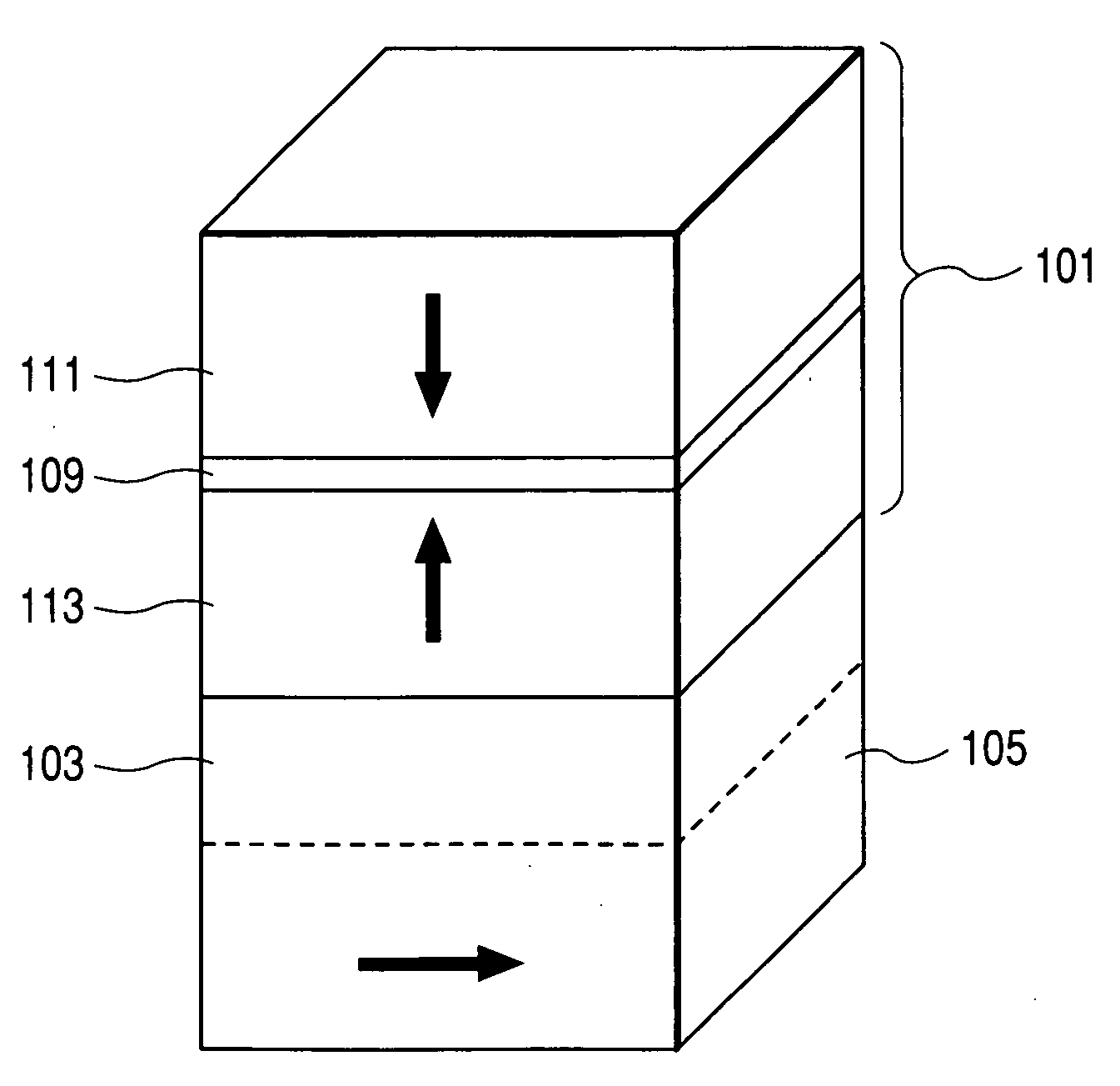
[0029]FIG. 4 illustrates an exemplary, non-limiting embodiment of a spin valve. A synthetic free layer 101 has a magnetization direction that is adjustable in response to an external magnetic field. More specifically, the synthetic free layer 101 includes a first free sublayer 111 having high perpendi...


PUM


Abstract

A magnetoresistive element is provided as a spin valve having a synthetic free layer. More specifically, the synthetic free layer includes a low perpendicular anisotropy layer that is separated from a high perpendicular anisotropy layer by a spacer. Thus, the high anisotropy material introduces an out-of-plane component by exchange coupling. The high perpendicular anisotropy material also has low spin polarization. Further, the low anisotropy material positioned closer to the pinned layer has a high spin polarization. As a result, the magnetization of the low anisotropy material is re-oriented from an in-plane direction to an out-of-plane direction. Accordingly, the overall free layer perpendicular anisotropy can be made small as a result of the low anisotropy material and the high anisotropy material. Adjusting the thickness of these layers, as well as the spacer therebetween, can further lower the anisotropy and thus further increase the sensitivity.

Description

BACKGROUND OF THE INVENTION [0001] 1. Technical Field [0002] The present invention relates to a magnetic head having an exchange-coupled free layer with out-of-plane magnetization. [0003] 2. Related Art [0004] In the related art magnetic recording technology such as hard disk drives, a head is equipped with a reader and a writer that operate independently of one another. The reader includes a free layer, a pinned layer, and a spacer between the pinned layer and the free layer. [0005] In the reader, the direction of magnetization in the pinned layer is fixed. However, the direction of magnetization in the free layer can be changed, for example (but not by way of limitation) depending on the effect of an external magnetic field, such as the recording medium. [0006] When the external magnetic field (flux) is applied to a reader, the magnetization direction of the free layer is altered, or rotated, by an angle. When the flux is positive, the magnetization of the free layer is rotated up...

Claims


Application Information

Patent Timeline
IPC IPC(8): G11B5/33G11B5/127
CPCB82Y10/00G01R33/093G11B5/3909H01F10/3286G11B2005/3996H01F10/3272H01L43/08G11B5/3929H10N50/10
Inventor SBIAA, RACHIDSATO, ISAMUMORITA, HARUYUKI
Owner TDK CORPARATION
Why Eureka
Try Eureka