Radiographic apparatus

a radiation apparatus and radiation sensitivity technology, applied in the field of radiation apparatus, can solve the problems of large radiation dose on the mammary gland with high radiation sensitivity, difficult to effectively acquire images by radiation rays, similar inconvenience, etc., and achieve the effect of efficiently utilizing radiation rays and easy acquisition of images

a radiation apparatus and radiation sensitivity technology, applied in the field of radiation apparatus, can solve the problems of large radiation dose on the mammary gland with high radiation sensitivity, difficult to effectively acquire images by radiation rays, similar inconvenience, etc., and achieve the effect of efficiently utilizing radiation rays and easy acquisition of images

US20060291614A1Inactive Publication Date: 2006-12-28GE MEDICAL SYST GLOBAL TECH CO LLC

Image

  • Radiographic apparatus
  • Radiographic apparatus
  • Radiographic apparatus

Examples


Embodiment Construction

[0019] An embodiment of the present invention will be described.

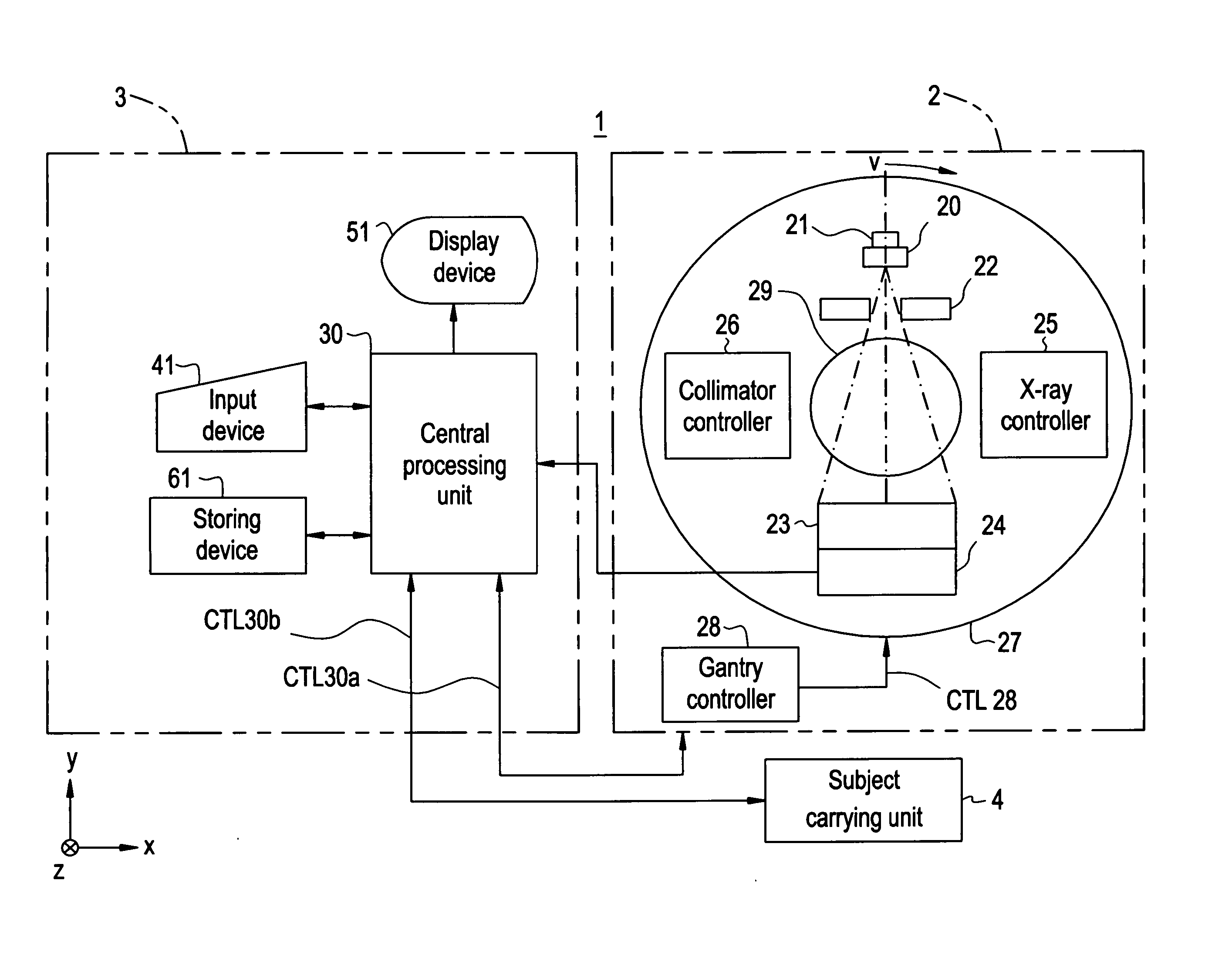
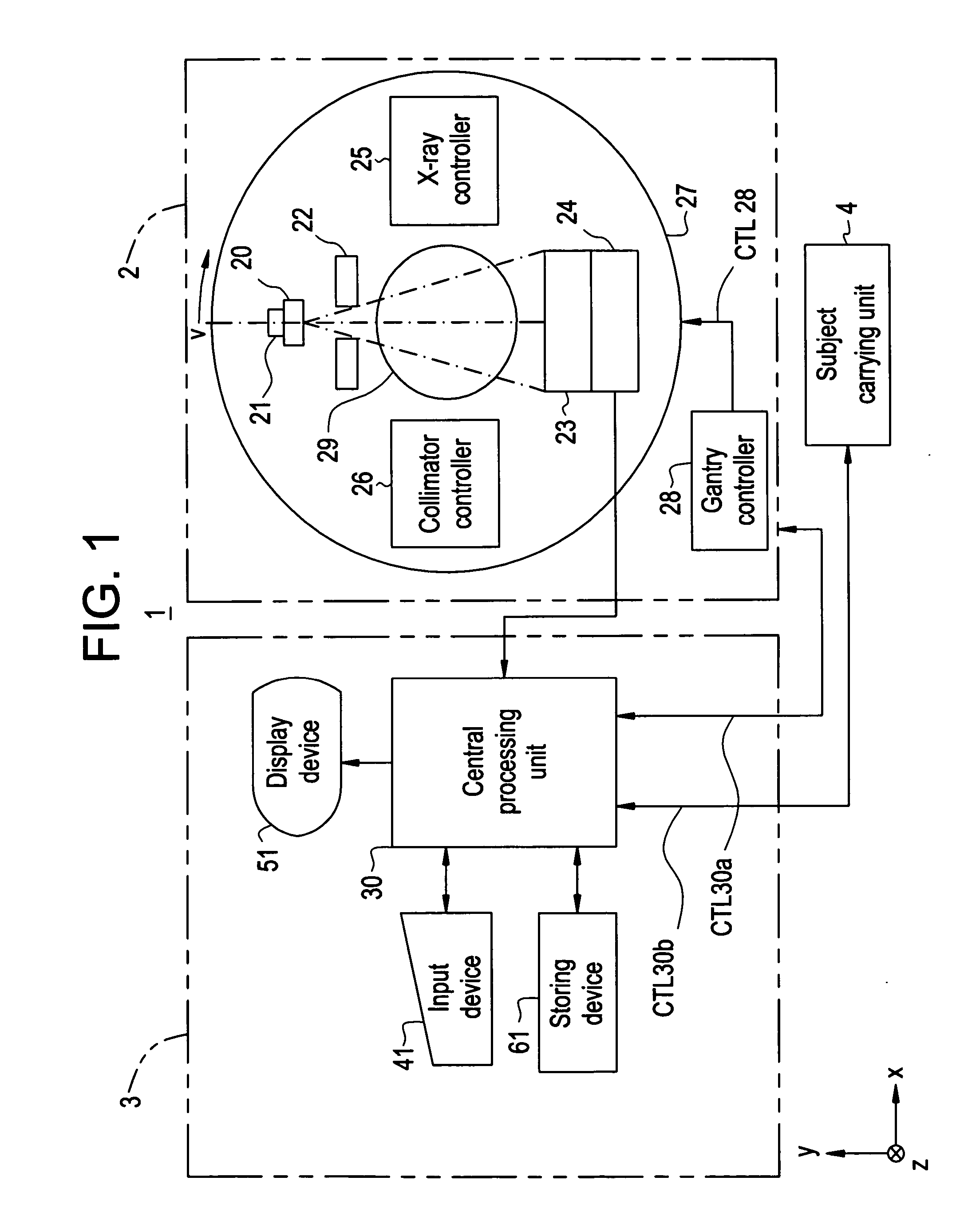
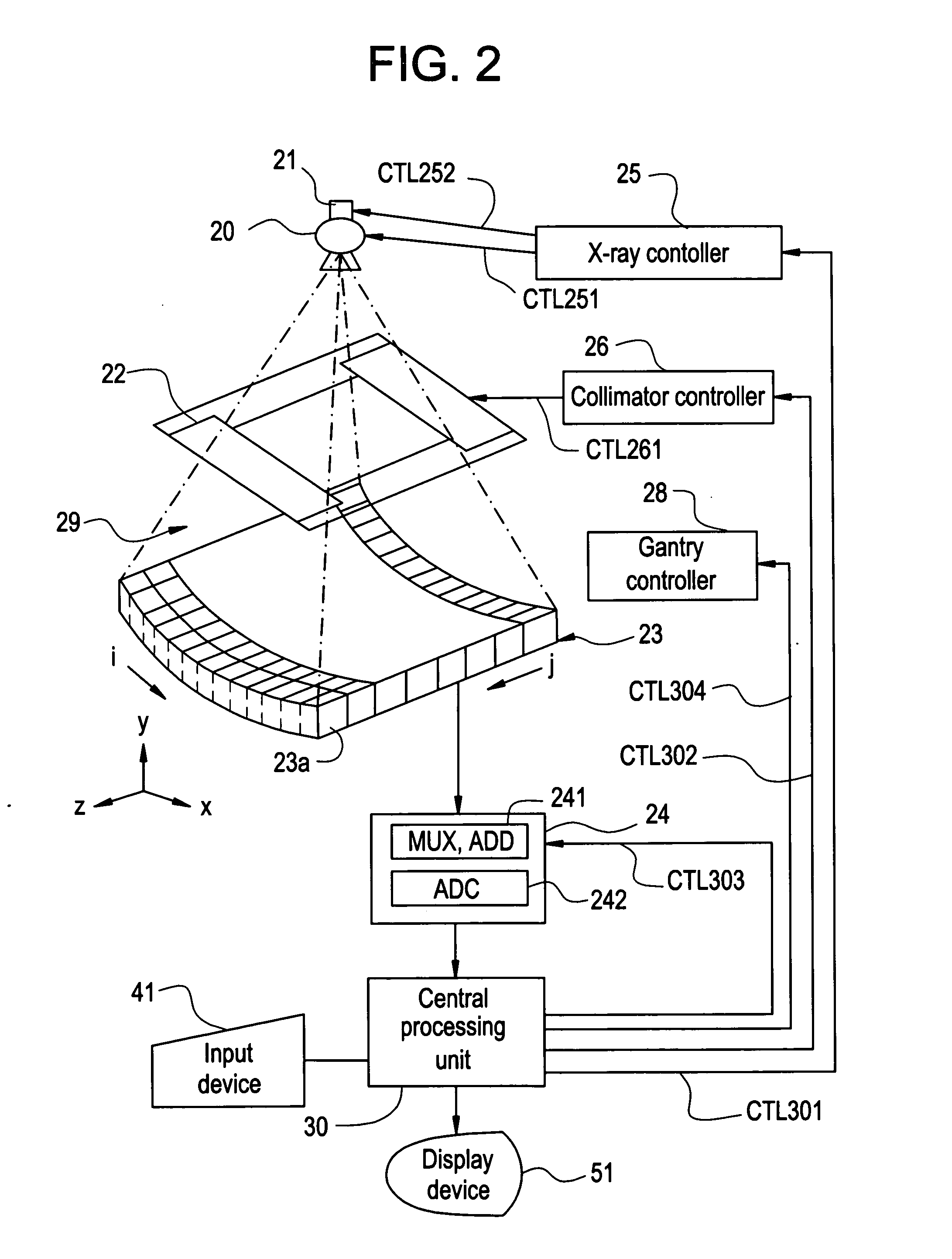
[0020]FIG. 1 is a block diagram showing a general configuration of an X-ray CT apparatus 1 of the embodiment according to the invention, and FIG. 2 is a configuration diagram showing a main part in the X-ray CT apparatus 1 of the embodiment.

[0021] As shown in FIG. 1, the X-ray CT apparatus 1 has a scan gantry 2, an operation console 3, and a subject carrying unit 4 and reconstructs and generates an image of a section of the subject by using projection data of the subject obtained by scanning the subject with an X-ray on the basis of scan parameters.

[0022] The scan gantry 2 will be described.

[0023] The scan gantry 2 obtains projection data of the subject by scanning the subject with X-rays, who is moved in a photographing space 29 by the subject carrying unit 4 on the basis of a control signal CTL30a from the operation console 3. As shown in FIG. 1, the scan gantry 2 has an X-ray tube 20, an X-ray tube moving unit 21...


PUM

PropertyMeasurementUnit
view angleaaaaaaaaaa
rotation movementaaaaaaaaaa

Abstract

To enable radiation rays to be efficiently used. A scout scan parameter setting unit sets a rotation movement position to which an X-ray tube and an X-ray detector are moved so as to rotate around a subject on the basis of subject information of a subject on which a scout scan is performed at the time of performing a scout scan. At the time of starting execution of the scout scan, a rotating unit moves the X-ray tube and the X-ray detector so as to rotate around the subject to the rotation movement position which is set by the scout scan parameter setting unit. After that, a scout scan is performed in the rotation movement position.

Description

BACKGROUND OF THE INVENTION [0001] The present invention relates to a radiographic apparatus and, more particularly, to a radiographic apparatus for generating a scout image of a subject by performing, in a rotation movement position to which an irradiator for applying radiation rays and a detector for detecting the radiation rays which have passed the subject are moved so as to rotate around the subject, a scout scan in which the irradiator irradiates the subject with radiation rays, and the radiation rays passed through the subject are detected by the detector. [0002] A radiographic apparatus such as an X-ray CT (Computed Tomography) apparatus generates a slice image of a section of a subject on the basis of projection data obtained by scanning the subject with radiation rays such as X-rays. Such a radiographic apparatus is used in wide-range applications such as medical and industrial applications. [0003] An X-ray CT apparatus performs a scout scan for generating a scout image in...

Claims


Application Information

Patent Timeline
28 Dec 2006
Publication
US20060291614A1
IPC
H05G1/60; A61B6/00; G01N23/00; G21K1/12
CPC
A61B6/032; A61B6/488; G01N2223/612; G01N23/046; G01N2223/419; A61B6/545
Inventors
HORIUCHI, TETSUYA; SEKIGUCHI, JUNKO