
X-ray radiation sources with low neutron emissions for radiation scanning

a radiation scanning and neutron emission technology, applied in the field of x-ray radiation sources, can solve the problems of increasing the size and cost of the system, reducing the efficiency of the system,

Inactive Publication Date: 2006-12-28
VAREX IMAGING CORP
View PDF15 Cites 14 Cited by
  • Summary
  • Abstract
  • Description
  • Claims
  • Application Information

AI Technical Summary

Benefits of technology

[0022] As used herein, the term “about” refers to differences due to round off errors and typical measurement capabilities; the term “at least one of” means “any one or more of the following”; the term “consisting essentially of” means that isotopes of other materials that will not generate neutrons at the peak acceleration energy of the source, may be included; and the term “peak acceleration energy” means “maximum” acceleration energy.

Problems solved by technology

However, radiation in the kilovolt range may not penetrate objects thicker than about 5 feet (1.52 meters), particularly if the object is filled with dense material.
The low energies used in typical X-ray luggage and bag scanners, described above, are generally too low to penetrate through the much larger cargo containers, particularly those with widths or thicknesses of 5 feet (1.5 meters) or more.
Since neutrons may be harmful to people proximate the scanning system, thicker shielding may be required to prevent the escape of neutrons from the scanning system or the room containing the scanning system.
This may increase the size and cost of the system.
It is said to be difficult to reduce the number of neutrons produced per useful photon rad of radiation, in the space available in existing sources.
It is noted that neutron emission may be reduced by absorbing unwanted neutrons in a medium Z material, such as iron, instead of tungsten or lead; but it is also noted that much more iron is required than tungsten or lead and there is insufficient space to take advantage of this reduction completely.

Method used


Image

  • X-ray radiation sources with low neutron emissions for radiation scanning
  • X-ray radiation sources with low neutron emissions for radiation scanning
  • X-ray radiation sources with low neutron emissions for radiation scanning

Examples


Embodiment Construction

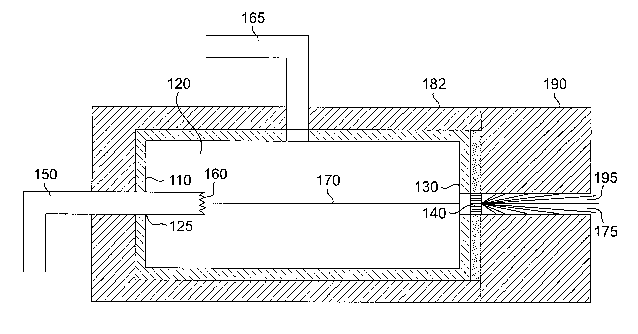
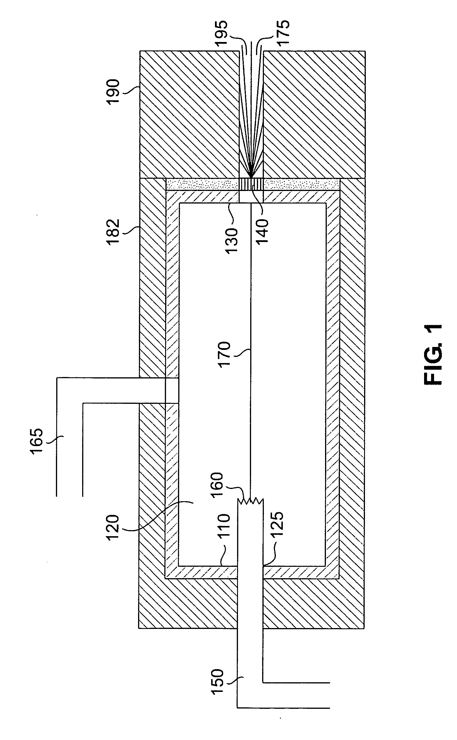
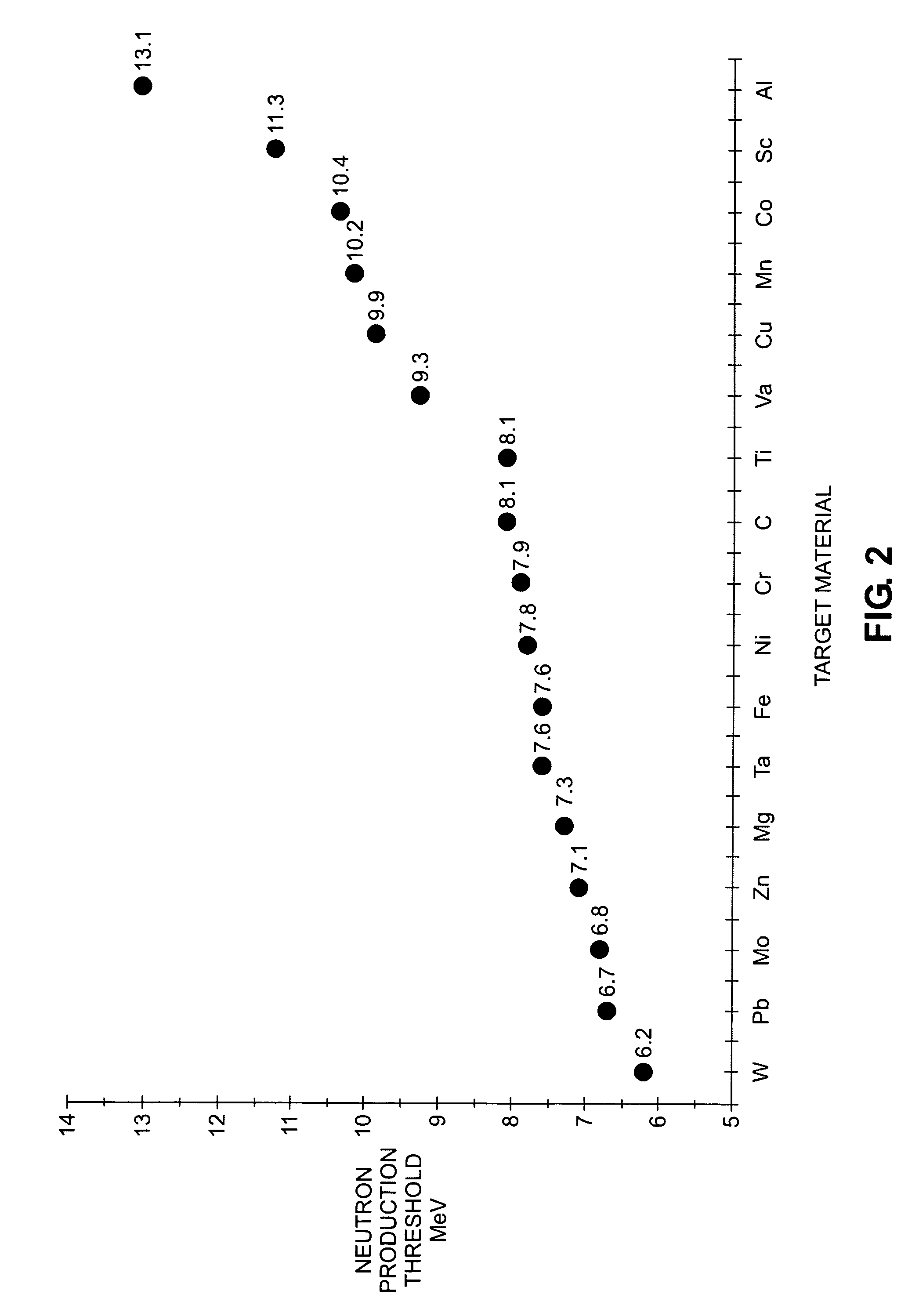
[0031] In accordance with embodiments of the invention, radiation sources, such as X-ray radiation sources, provide no neutron production or reduced neutron production as compared to radiation sources comprising typical materials for the source, collimator, and / or shielding by using materials with neutron production thresholds above the peak acceleration energy of the source. (As mentioned above, here, the term “peak acceleration energy” means “maximum” acceleration energy.) For example, an X-ray source with a peak acceleration energy of less than about 9.9 MeV, comprising a copper target, a copper collimator, and copper shielding of the target and housing, will generate no neutrons. Where it is not feasible to use only materials with neutron production thresholds below the peak acceleration energy of the source due to size, weight, and / or cost constraints, neutron production may be reduced by using such materials for all or part of certain components. By proper selection of materia...


PUM

PropertyMeasurementUnit
peak acceleration energyaaaaaaaaaa

Abstract

In one example, a radiation source comprises a housing and an acceleration chamber within the housing, with a peak acceleration energy greater than the lowest neutron production threshold of tantalum. A source of charged particles is supported by the housing to emit charged particles into the acceleration chamber. A target is supported by the housing downstream of the acceleration chamber. The target consists essentially of at least one isotope having a neutron production threshold greater than the peak acceleration energy. No neutrons are therefore generated. The source may also comprise a collimator, target shielding, and / or housing shielding comprising at least one isotope having a neutron production threshold greater than the peak acceleration energy, reducing or eliminating neutron generation as compared to the prior art, as well. Systems comprising the source, methods of operation of the source, and methods of manufacture of the source are also disclosed.

Description

FIELD OF THE INVENTION [0001] X-ray radiation sources and, more particularly, X-ray radiation sources with low neutron emissions for radiation scanning of objects. BACKGROUND OF THE INVENTION [0002] X-ray radiation sources are commonly used in radiation inspection systems for non-destructive inspection of objects. X-ray radiation may be generated in such sources by the impact of a beam of accelerated electrons on a high atomic number (“Z”) target material, such as tungsten or tantalum. The electrons are accelerated by a potential difference established across a chamber, referred to as an acceleration energy. The deceleration of the incident electrons by the nuclei of the atoms of the target material generates radiation, referred to as Bremsstrahlung. A collimator is provided to direct some of the generated radiation onto an object to be inspected and to form the generated radiation into a beam of a desired size and shape. One or more radiation detectors are provided to measure radia...

Claims


Application Information

Patent Timeline
Patent Type & Authority Applications(United States)
IPC IPC(8): H01J35/08
CPCY10T29/531G01N23/005
Inventor CLAYTON, JAMES E.
Owner VAREX IMAGING CORP
Learn More