
Leveling blade, vibrating screed including the blade, and kit for assembling the same

Inactive Publication Date: 2006-12-28
PIRANDELLO INDS
View PDF32 Cites 17 Cited by
  • Summary
  • Abstract
  • Description
  • Claims
  • Application Information

AI Technical Summary

Benefits of technology

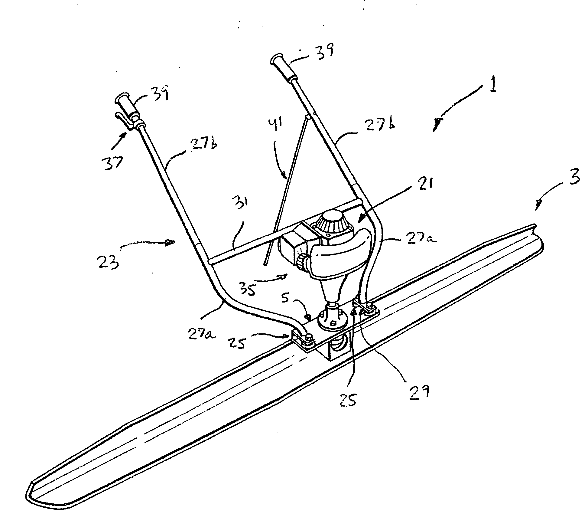
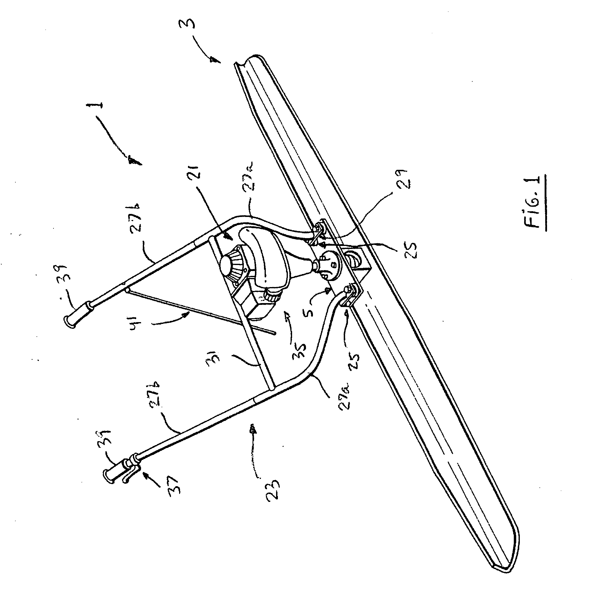
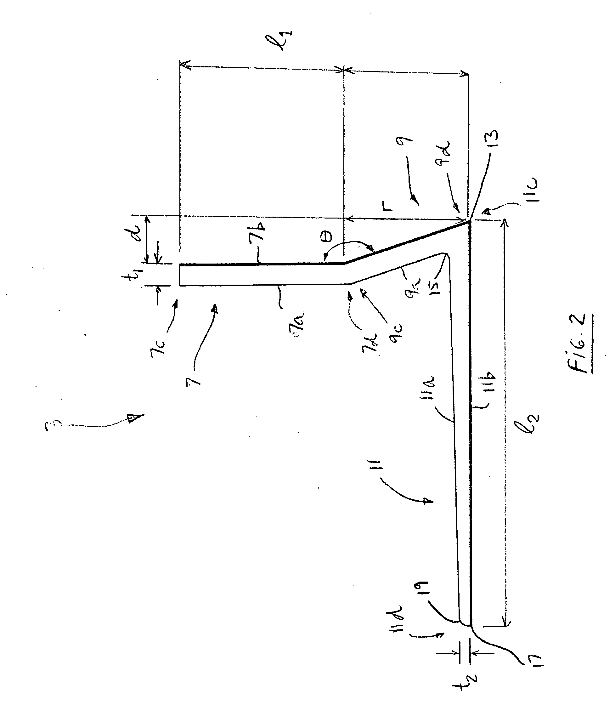
[0015] Preferably also, transitions between adjacent portions of the leveling blade and the second end of the substantially horizontal portion thereof are substantially rounded off, for allowing namely, but not limitedly, a smoother surfacing of a malleable material (concrete, etc.) with the leveling blade, so as to overcome undesirable accumulations and / or streaks known to occur with conventional leveling blades.

Problems solved by technology

It is also known in the art that a substantial drawback associated with these types of conventional vibrating screeds is that the profile of the blades used is not optimal (very often, they have a “segmented” profile), which results in an undesirable rearwardly accumulation of material behind the blade as it is passed over the material to be leveled.
Moreover, very often, the vibratory movement which is transmitted to the blade is also transmitted to the handles of the apparatus, and thus onto the hands of the user, which is undesirable for obvious reasons.
Moreover, it can be seen that the handle bars of such a conventional vibrating screed take up a lot of space, which is disadvantageous for storing purposes, and / or cannot be easily adjusted to allow a more ergonomic use of the vibrating screed for each individual user that may present different physical features or capabilities.
Moreover, another substantial drawback associated with vibrating screeds of the prior art is that the general design is such that the components thereof may not be easily interchanged in the event of maintenance and / or repair.

Method used


Image

  • Leveling blade, vibrating screed including the blade, and kit for assembling the same
  • Leveling blade, vibrating screed including the blade, and kit for assembling the same
  • Leveling blade, vibrating screed including the blade, and kit for assembling the same

Examples


Embodiment Construction

[0059] In the following description, the same numerical references refer to similar elements. The embodiments, geometric configurations and dimensions shown in the figures and / or presented herein, are preferred and for exemplification purposes only.

[0060] Moreover, although the present invention was primarily designed for leveling surface of concrete and the like, prior to hardening thereof, it may be used with other types of screeds and objects, and in other fields, as apparent to a person skilled in the art. For this reason, expressions such as “concrete”, “leveling”, “surfacing”, “floor”, “vibrating”, etc. used herein should not be taken as to limit the scope of the present invention and includes all other kinds of screeds, blades or items, and all other purposes, with which the present invention could be used and may be useful.

[0061] Moreover, in the context of the present invention, the expressions “screed”, “blade”, “device”, “unit”, “asembly”, and any other equivalent expre...


PUM


Abstract

A leveling blade for mounting onto a support bracket of a vibrating screed, and a vibrating screed including the same. The leveling blade has a substantially vertical portion for mounting onto the support bracket, as well as a substantially slanted portion and a substantially horizontal portion, which results in the leveling blade having a particular profile. The vibrating screed includes also a vibration-generating assembly, being operatively mounted onto the support bracket of the vibrating screed for imparting vibrations to the leveling blade via the support bracket so as to enable to carry out a surfacing of a substantially malleable material with the vibrating screed by passing said leveling blade provided with vibrations about said substantially malleable material. A kit is also provided for assembling such a vibrating screed.

Description

[0001] The present application claims priority of U.S. provisional patent application No. 60 / 694,262 filed Jun. 28th, 2005, the content of which is incorporated herein by reference.FIELD OF THE INVENTION [0002] The present invention relates to a leveling blade and to a vibrating screed provided with such a blade. More particularly, the present invention relates to a vibrating screed such as the ones used for surfacing concrete and other like materials, and also relates to a kit for assembling the same, as well as to a method of use or operation associated thereto. BACKGROUND OF THE INVENTION [0003] Vibrating screeds are very well known in the art. Indeed, they are generally used for leveling off a horizontal surface such as a floor, typically made of a malleable material, such as concrete and the like, prior to the hardening thereof. FIG. 1 of U.S. Pat. No. 6,296,467 B1 shows an example of a conventional vibrating screed. As can be easily understood from this figure, a blade is pass...

Claims


Application Information

Patent Timeline
IPC IPC(8): E01C19/22
CPCE04F21/24E01C19/402E04F21/242
Inventor ARGENTO, MICHELEARGENTO, SETTIMIO
Owner PIRANDELLO INDS
Learn More