Magnetocaloric pump for microfluidic applications

Inactive Publication Date: 2006-12-28
UT BATTELLE LLC
View PDF0 Cites 18 Cited by
  • Summary
  • Abstract
  • Description
  • Claims
  • Application Information

AI Technical Summary

Problems solved by technology

There are two limitations to such approaches.
First, the fluid flow is not continuous but pulsating.
Second, the pump deforms a membrane at high frequency.
Material fatigue limits the l

Method used


Image

  • Magnetocaloric pump for microfluidic applications
  • Magnetocaloric pump for microfluidic applications
  • Magnetocaloric pump for microfluidic applications

Examples


embodiment

Cooling Embodiment

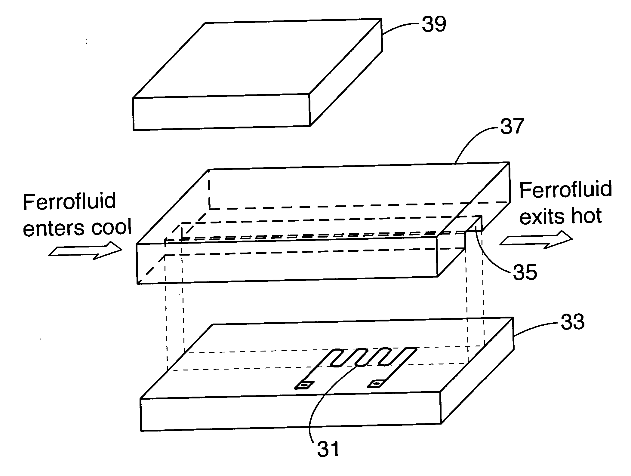
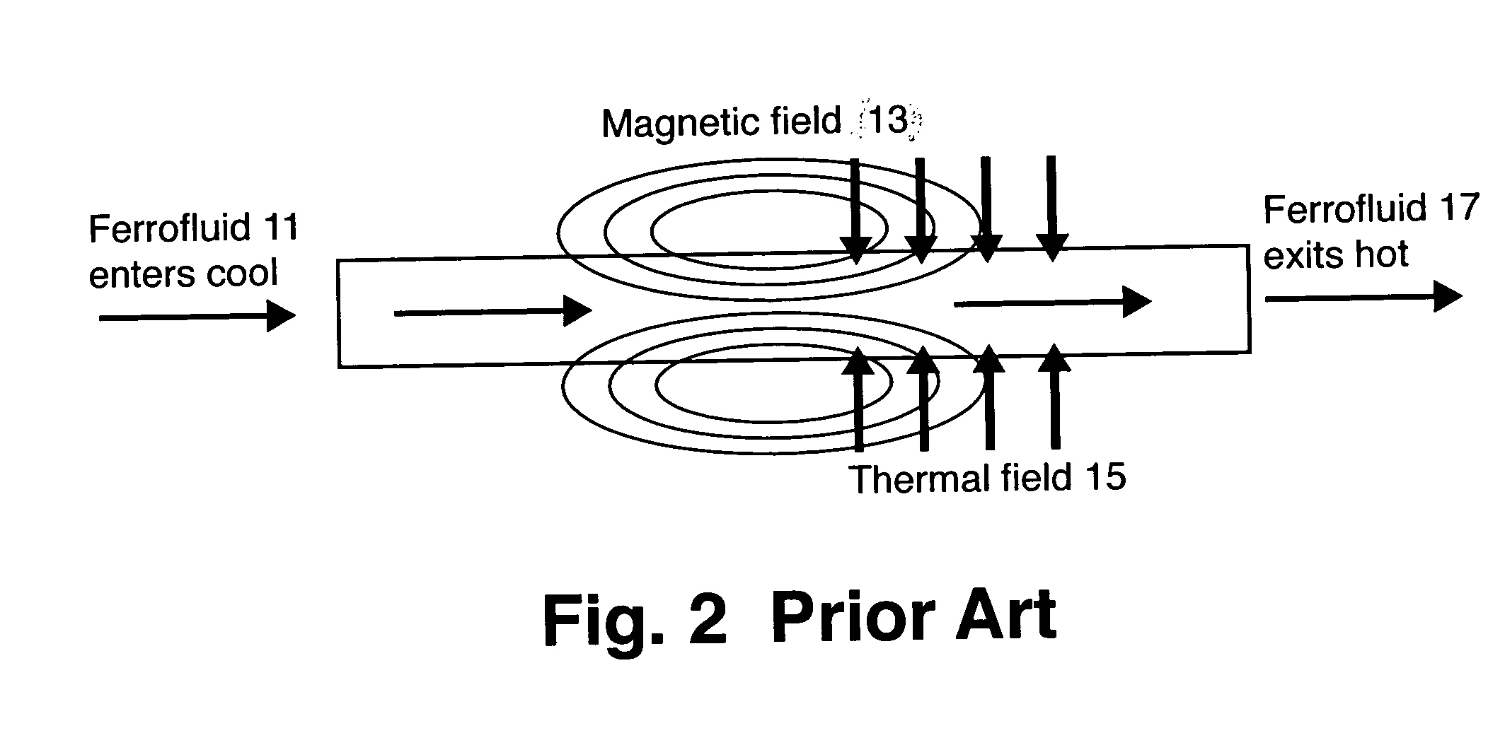
[0046] The basic principle for cooling is exactly the same as the pump except now the fluid acts as a convective heat exchanger taking heat away from a hot component, represented by the thermal field in FIG. 2 or the heat source in FIG. 6. As in the pump embodiment, cool fluid is attracted to the magnet. The hot component heats the fluid which subsequently loses it's attraction to the magnetic field and is displaced by cooler fluid. Subsequently, the pump is now acting as a heat pump removing heat from the hot component. The advantage of such an approach is 1) no moving mechanical parts and 2) self regulating control. As the hot component increases in temperature, the fluid flow will increase naturally, increasing the heat removal rate.

[0047] All electromagnetic actuators have coincident magnetic and thermal fields. The maximum operating torque of electric actuators is limited due to thermal constraints on the coils. Using this invention, it is possible to cool an...


PUM


Abstract

A microfluidic magnetocaloric pump. The magnetic and thermal properties of a ferrofluid such as MnZnFe2O4 nanoparticles in an oil- or water-based medium are allowed to interact with a magnetic field that is partially coincident with a thermal gradient. As the ferrofluid heats, it loses its attraction to the magnetic field and is displaced by cooler fluid. The micropump produces fluid propulsion with no moving mechanical parts while requiring only 35 mW power and operation at a temperature of only 40-80° C.

Description

STATEMENT REGARDING FEDERALLY SPONSORED RESEARCH OR DEVELOPMENT [0001] The United States Government has rights in this invention pursuant to Contract No. DE-AC05-00OR22725.between the United States Department of Energy and UT-Battelle, LLC.BACKGROUND OF THE INVENTION [0002] 1. Field of the Invention [0003] The present invention relates to microfluidic pumps. More particularly, a magnetocaloric pump incorporated into an integrated circuit chip utilizes MnZnFe2O4 ferrofluid. The micropump requires only 35 mW power and operates at a temperature of only 40-80° C. [0004] 2. Description of the Prior Art [0005] Microfluidic and lab-on-a-chip devices usually require some form of fluid pumping mechanism. While a great many pumping methods are known, there are only two basic approaches to pumping fluid at the microfluidic level. These are diaphragm and field-induced pumps. Diaphragm pumps use a small diaphragm on the chip that undergoes deformation to move the fluid. Passive valves or restric...

Claims


Application Information

Patent Timeline
IPC IPC(8): F04B19/24
CPCF04B19/24F04B19/006
Inventor LOVE, LONNIE J.JANSEN, JOHN F.MCKNIGHT, TIMOTHY E.
Owner UT BATTELLE LLC
Why Eureka
Try Eureka