Apparatus and method for inhibiting pain signals transmitted during a skin related medical treatment

Inactive Publication Date: 2006-12-28
CANDELA CORP
View PDF60 Cites 158 Cited by
  • Summary
  • Abstract
  • Description
  • Claims
  • Application Information

AI Technical Summary

Benefits of technology

[0028] As referred to herein, a “medical treatment” is a procedure administered to a living subject to improve a pathological disorder, to improve the appearance of a

Problems solved by technology

The treatment of skin is often very painful and may necessitate the utilization of analgesic topical creams such as EMLA cream produced by AstraZeneca Inc., Canada, or even of anesthetic injections to inhibit the pain.
Such pain inhibiting procedures are risky and also increase the total duration of the treatment.
This localized increase in temperature also causes a pain sensation.
The ultrasonic frequency of most treatments is in the 1-10 MHz range, and the focused ultrasonic treatments are generally very painful.
Hair removal by means of an ultrasonic device is generally very painful.
Another disruptive treatment which is liable to cause pain is the vibration of hair at a frequency equal to, or slightly greater than, sonic frequency.
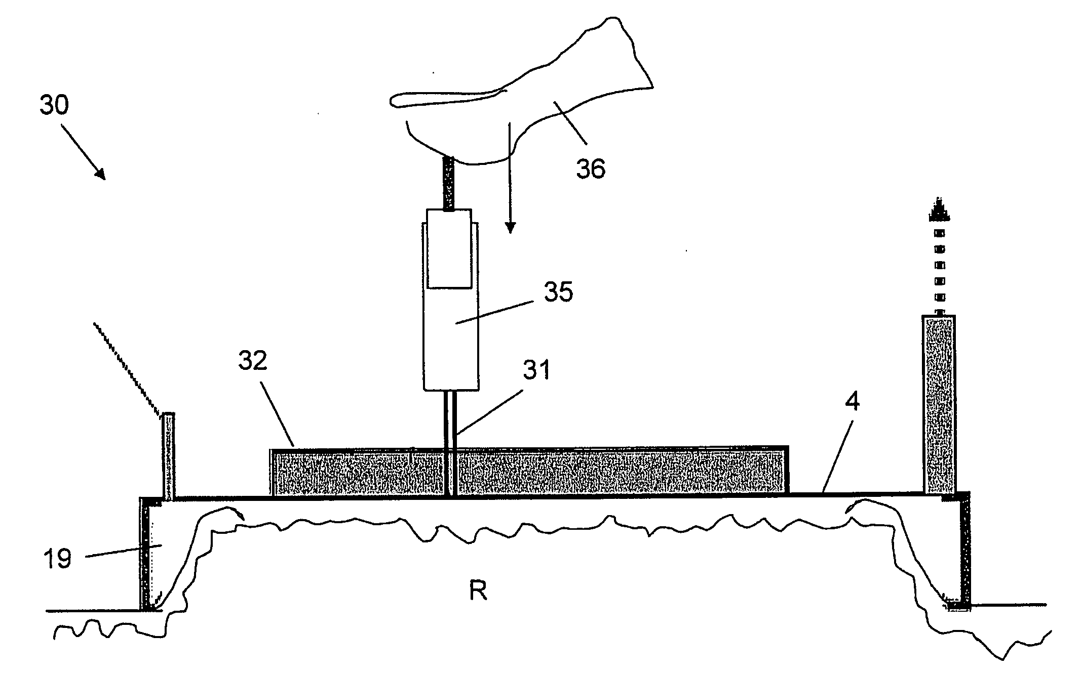
Another medical treatment that is generally painful is the subcutaneous injection of a medication by means of a needle, causing much apprehension to patients prior to the injection.
The deficiencies of this device with respect to pain inhibition include a low pain reduction, lack of repeatability, and considerable inconvenience to the patient.
Some of the disadvantages of this method include the difficulty and inconvenienc

Method used


Image

  • Apparatus and method for inhibiting pain signals transmitted during a skin related medical treatment
  • Apparatus and method for inhibiting pain signals transmitted during a skin related medical treatment
  • Apparatus and method for inhibiting pain signals transmitted during a skin related medical treatment

Examples


example 1

[0162] The pain level distribution resulting from a light-based, vacuum-assisted skin flattening skin treatment was compared to that resulting from a conventional light-based skin treatment. The light that was generated was suitable for hair removal, emitting pulses of light which were absorbed by hair follicles. The sharp burn sensation that was felt when a vacuum was not applied simulated the pain sensation which is normally associated with the injection of a needle through a skin region.

[0163] Light generated by an IPL Lovely unit manufactured by Msq Ltd., Israel and having an energy density of 18 J / cm2, a wavelength greater than 640 nm, and a pulse duration of 30 msec was directed to 41 different skin targets. Light generated by an Alexandrite laser unit having an energy density of 25 J / cm2 and a pulse duration of 3 msec was directed to 2 different skin targets. Light generated by a diode laser having an energy density of 42 J / cm2 and a pulse duration of 2 msec was directed to ...

example 2

[0165] The influence of the vacuum level during a skin flattening skin treatment on the perceived pain level was tested. Light generated by an IPL Lovely unit manufactured by Msq Ltd., Israel and having an energy density of 18 J / cm2, a wavelength greater than 640 nm, and a pulse duration of 30 msec was directed to 10 different skin targets. The pain sensation was evaluated according to a modified McGill pain questionnaire. Table I below reflects the average pain level reduction that was perceived for the different vacuum levels that were applied to each of the 10 skin targets.

[0166] At a vacuum level of approximately 150 mmHg, the perceived average pain level was 4. The perceived pain level was further reduced to a pain level of 3 when a vacuum level of 300 mmHg was applied, and a significant pain reduction to a pain level of 2 was achieved when a vacuum level of 500 mmHg was applied.

TABLE IApplied Vacuum (mmHg)Level of Pain Reduction 0010002000300140015002

example 3

[0167] The influence of the surface area of the transmitting element during a skin flattening skin treatment on the perceived pain level was tested. Light generated by an IPL Lovely unit manufactured by Msq Ltd., Israel and having and energy density of 18 J / cm2, a wavelength greater than 640 nm, and a pulse duration of 30 msec was directed to 10 different skin targets. Light generated by a diode laser having an energy density of 42 J / cm2 and a pulse duration of 2 msec was directed to 2 different skin targets. The vacuum level that was applied to each of the skin targets was 500 mmHg. The pain sensation was evaluated according to a modified McGill pain questionnaire.

[0168] For a rigid surface of 9×9 mm, the average perceived pain level was 3. For a rigid surface of 12×20 mm, the average perceived pain level was a tolerable 2-3. For a rigid surface of 20×40 mm, the average perceived pain level was 1-2, which was nearly without any pain.


PUM


Abstract

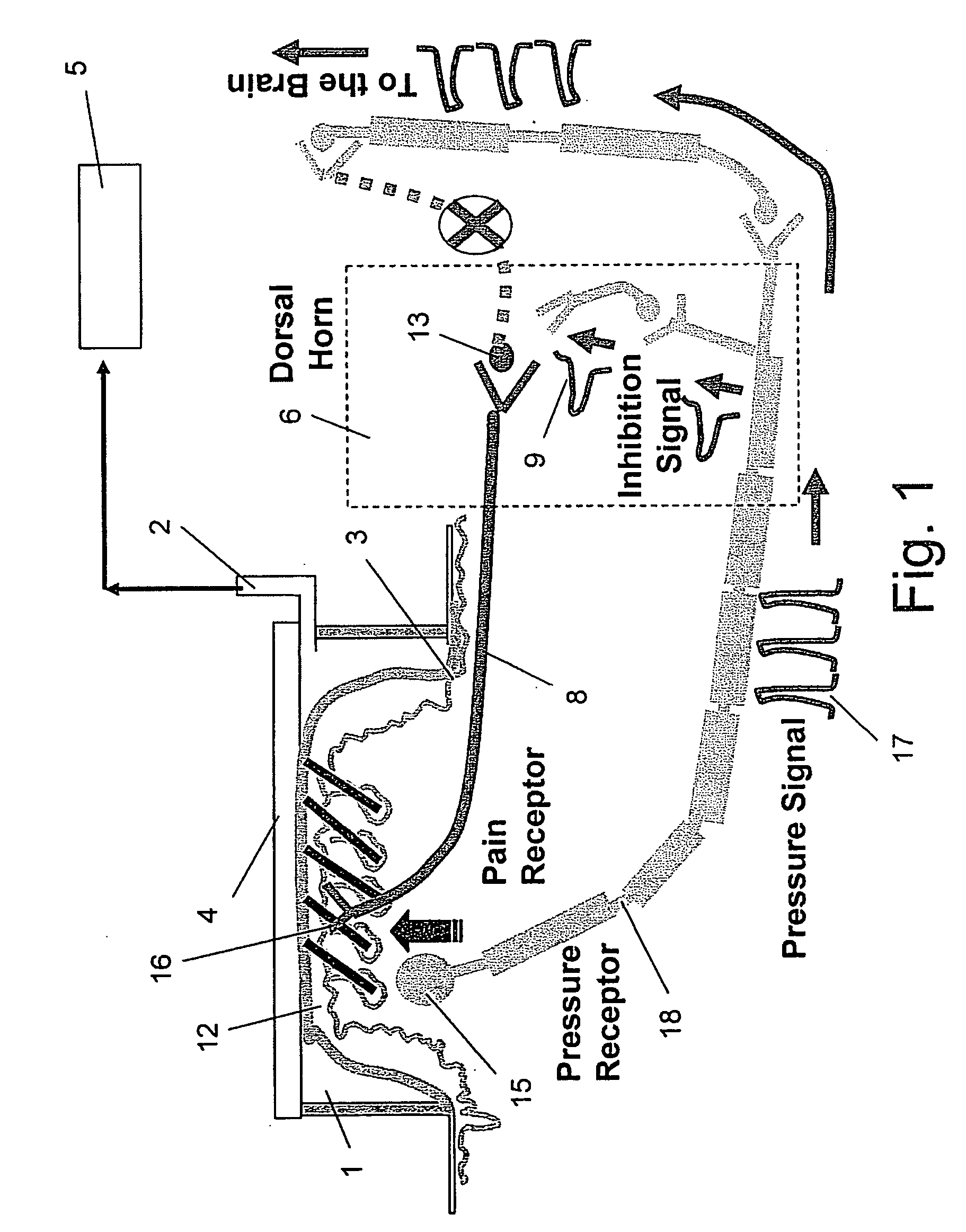
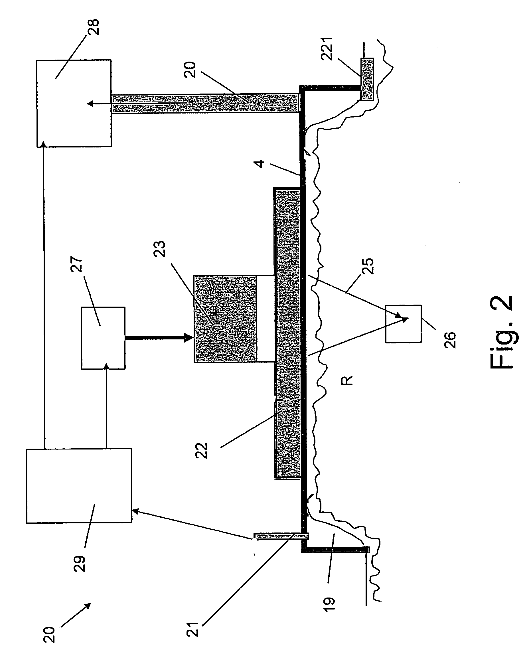
An apparatus adapted to inhibit pain signals generated by pain receptors in the skin during a skin related medical treatment such as an injection. An evacuation chamber is provided with an essentially rigid interface element larger than a threshold surface area through which a medical treatment can be administered to a selected skin region, one or more walls which are placeable in the vicinity of the skin region, an interior defined by the walls and by the interface element, and an opening at the bottom of the interior which is sealable by the skin region. A device generates a vacuum within the evacuation chamber interior to a level greater than the threshold vacuum level suitable for drawing the skin region through the opening towards, and in a compressing relation against, the interface element, to inhibit the transmission of a pain signal generated by pain receptors located within the skin region.

Description

[0001] This application claims priority from IL Patent Application No. 170132 (filed Aug. 4, 2005), now abandoned, IL Patent Application No. 174847 (filed Apr. 6, 2006), and IL Patent Application No. 175486 (filed May 8, 2006), and is a Continuation-In-Part of the U.S. patent application Ser. No. 11 / 401,674 (filed Apr. 11, 2006), which claims priority from EP Patent Application No. 050007952.4 (filed Apr. 12, 2005) is a Continuation-In-Part of U.S. patent application Ser. No. 11 / 057,542 (filed Feb. 14, 2005), which claims priority from Israeli Patent Application No. 160510 (filed on Feb. 22, 2004) and is a Continuation-In-Part of U.S. patent application Ser. No. 10 / 498,382 (filed Jun. 10, 2004), which is a Continuation-In-Part of PCT / IL02 / 00635 (filed on Aug. 2, 2002), which is derived from IL 147009 (filed on Dec. 10, 2001) and from IL 150094 (filed on Jun. 6, 2002).FIELD OF INVENTION [0002] The current invention is related to an apparatus adapted to inhibit the sensation of pain d...

Claims


Application Information

Patent Timeline
IPC IPC(8): A61N1/00A61B18/20A61H23/02A61N5/06A61N5/067
CPCA61B17/205A61B2018/00994A61B18/203A61B2017/00747A61B2017/00752A61B2017/306A61B2018/00005A61B2018/00291A61B2018/00452A61B2018/00458A61B2018/00476A61H7/008A61H9/005A61H9/0057A61M5/422A61M5/425A61N7/00A61N2007/0008A61B18/14
Inventor SLATKINE, MICHAELSHAVIT, RAPHAEL
Owner CANDELA CORP
Why Eureka
Try Eureka