
Pressure activated disconnect lock coupling

Active Publication Date: 2007-01-04
THE GATES CORP
View PDF35 Cites 19 Cited by
  • Summary
  • Abstract
  • Description
  • Claims
  • Application Information

AI Technical Summary

Benefits of technology

[0012] The present invention substantially meets the aforementioned needs of the industry and limitations of the prior art. One embodiment of the present invention provides a quick connect coupling that utilizes the internal fluid pressure to deform a wedging ring into a groove on either a male portion or a female portion of the coupling, thus locking the portions together and stabilizing the coupling until the internal pressure is released. Such an embodiment may include the male portion for selective interconnection with the female portion, and which is retained in a locked position by a pressure activated wedging ring. The engagement and disengagement noted above is generally achieved without the use of tools to ensure that the system remains locked. In one embodiment, a pressure activated wedging ring is provided which substantially prevents disengagement of the male portion from the female portion when the coupling is internally pressurized. More specifically, embodiments of the present invention utilize the internal pressure of the system to deform the wedging ring. The wedging ring may either decrease or increase in diameter to seat into a groove located in the female portion of the coupler or into a groove in the male portion of the coupler, thus preventing removal of the two portions of the coupling when pressure is introduced into the system. One skilled in the art will appreciate that the wedging ring is fabricated from resiliently deflectable materials, the selection of which will dictate the amount of pressure required for deflection and the extent of deflection. It is thus an aspect of the present invention to provide a quick connect hose coupling with an improvement in safety while retaining the economical and functional benefits of quick connect couplings.
[0013] It is another aspect of the present invention to provide a coupler that includes a male coupling portion and a female coupling portion. The female portion generally interconnects to a fixed port, or adapter for engagement with a port, such as a commonly known hexhead fluid boss. The male portion interconnects generally to a flexible fluid line, and selectively interconnects with the female portion. The female portion in one embodiment also includes a locking device such that the coupler cannot be disconnected when the system is internally pressurized. The present invention is generally interconnected without the need of tools such as wrenches or auxiliary external locking devices. In addition, the coupled system decreases the chance of a hydraulic hose kinking because the coupled portions may generally be rotated with respect to each other while remaining locked.
[0017] It is yet another aspect of the present invention to provide a coupling that is generally comprised of commonly known materials. More specifically, the wedging ring of one embodiment of the present invention is a resiliently deflectable material comprised of steel, aluminum, silicone, or combinations thereof. The wedging ring is generally placed in a widened seal groove that is located in the male portion or female portion of the coupling. Seal grooves of existing couplings may be easily retrofitted by minimal machining operations to accommodate the pressure activated wedging ring and associated angled surface that is used for deflection purposes. Thus, it is one aspect of the present invention to provide a quick connect coupling with a pressure activated locking assembly which generally comprises:
[0021] a pressure activated locking device for interaction with at least one of said female coupling and said male coupling that deflects when said quick connect coupling is pressurized, wherein disconnection of said male coupling and said female coupling is substantially prevented until a release of a predetermined amount of pressure, preferably, said male coupling is thereby stabilized relative to said female coupling when said quick connect is pressurized.

Problems solved by technology

In addition, the coupled system decreases the chance of a hydraulic hose kinking because the coupled portions may generally be rotated with respect to each other while remaining locked.
Thus, the coupler cannot be disconnected when it is pressurized.

Method used


Image

  • Pressure activated disconnect lock coupling
  • Pressure activated disconnect lock coupling
  • Pressure activated disconnect lock coupling

Examples


Embodiment Construction

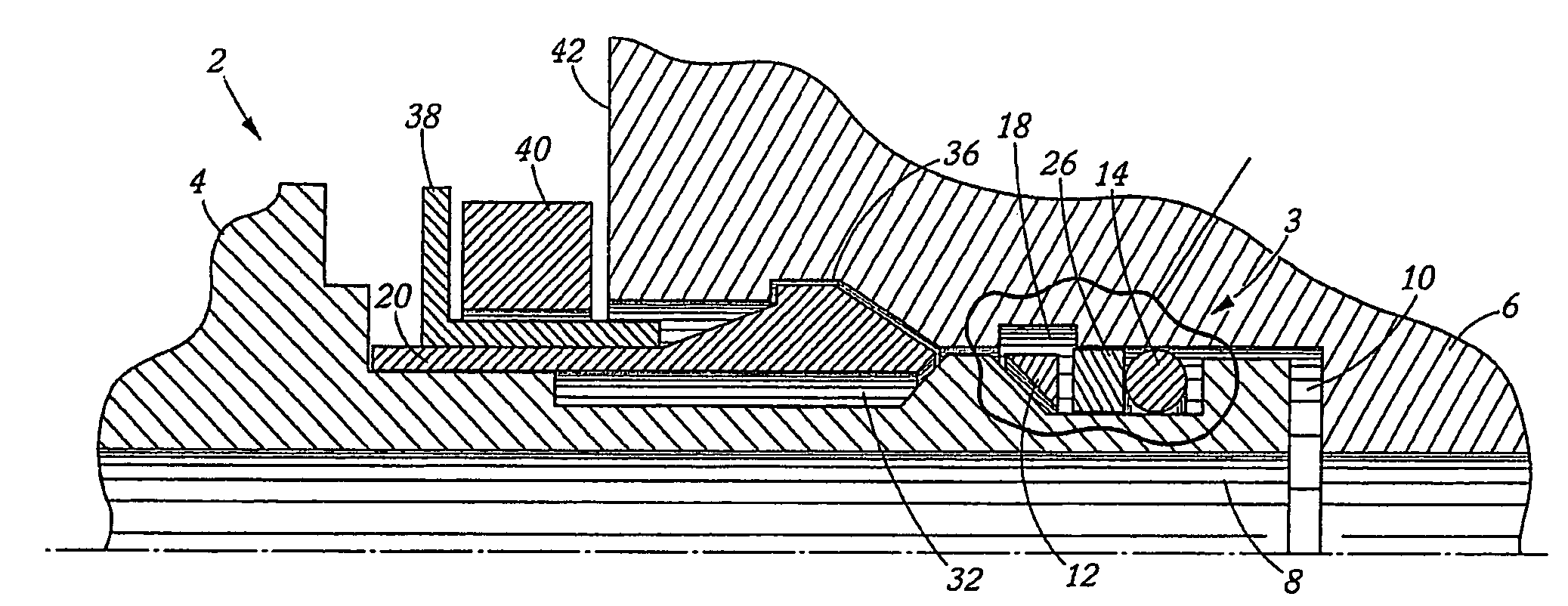
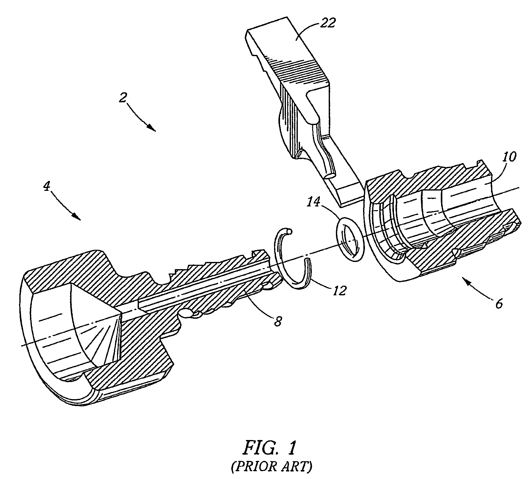
[0040] Referring now to FIG. 1, an example of a prior art quick connect coupling 2 is shown. More specifically, hydraulic and pneumatic quick connect couplings generally include a female portion 6 that is typically a cylindrical shaped member with an inner diameter and an outer diameter such that liquids and / or gases may pass freely therethrough. Quick connects also include a male portion 4 that operably engages the female portion 6. The male portion 4 has a plurality of grooves where at least one seal 14 and / or locking device 12 may be interconnected. The outer diameter of the male portion 4 is generally less than the inner diameter of the female portion 6 of the coupling 2 to allow selective engagement and disengagement of the coupling. In order to maintain the integrity of the quick connect, a spacer 22 may be used to prevent unwanted deflection of the male portion 4 into the female portion 6. More specifically, once the wedging ring 12 is deformed, it engages a cavity in the fem...


PUM


Abstract

A coupling assembly is provided herein which generally includes a female coupler selectively interconnected to a male coupler to provide sealing engagement. In one embodiment, the female coupler and the male coupler are secured together by a pressure activated locking assembly which prevents disengagement of the male and female coupling until the internal pressure in the coupling is reduced to a predetermined level.

Description

[0001] This patent application claims the benefit of U.S. Provisional Patent Application Ser. Nos. 60 / 660,894 and 60 / 660,971, both filed Mar. 11, 2005, which are incorporated by reference in their entirety herein.FIELD OF THE INVENTION [0002] The present invention relates generally to couplings that can be selectively connected and disconnected without the need of tools. More specifically, the invention relates to a quick connect coupling assembly that substantially prevents disengagement of a male portion and a female portion when the coupling is exposed to internal pressure. BACKGROUND OF THE INVENTION [0003] Quick connect hydraulic couplings typically include a male portion in operable engagement with a female portion. The male and female portions may be interconnected to a hydraulic hose, tubing, piping, machinery or open apparatus that utilizes internal pressure. Since many of these hydraulic hoses and interconnecting machinery utilize high pressure fluids, safety and operation...

Claims


Application Information

Patent Timeline
IPC IPC(8): F16L37/06
CPCF16L37/002F16L37/088F16L37/06F16L37/0887
Inventor SWIFT, JONATHAN C.KEAST, GEOFFREY R.ROBINSON, TIMOTHY G.MCGEE, STEPHEN
Owner THE GATES CORP
Features
  • Generate Ideas
  • Intellectual Property
  • Life Sciences
  • Materials
  • Tech Scout
  • Unparalleled Data Quality
  • Higher Quality Content
  • 60% Fewer Hallucinations
Learn More