Axial air-gap electronic motor

Active Publication Date: 2007-01-04
FUJITSU GENERAL LTD
View PDF11 Cites 23 Cited by
  • Summary
  • Abstract
  • Description
  • Claims
  • Application Information

AI Technical Summary

Benefits of technology

[0028] According to this configuration, since the winding protective portion for covering a part of the side surface of the stator iron core is provided in a p

Problems solved by technology

However, since this assembling process is a temporary one for putting the core members in a mold for the next resin molding, the core members are easily disconnected by a slight shock.
Also, after the coil has been w

Method used


Image

  • Axial air-gap electronic motor
  • Axial air-gap electronic motor
  • Axial air-gap electronic motor

Examples


Embodiment Construction

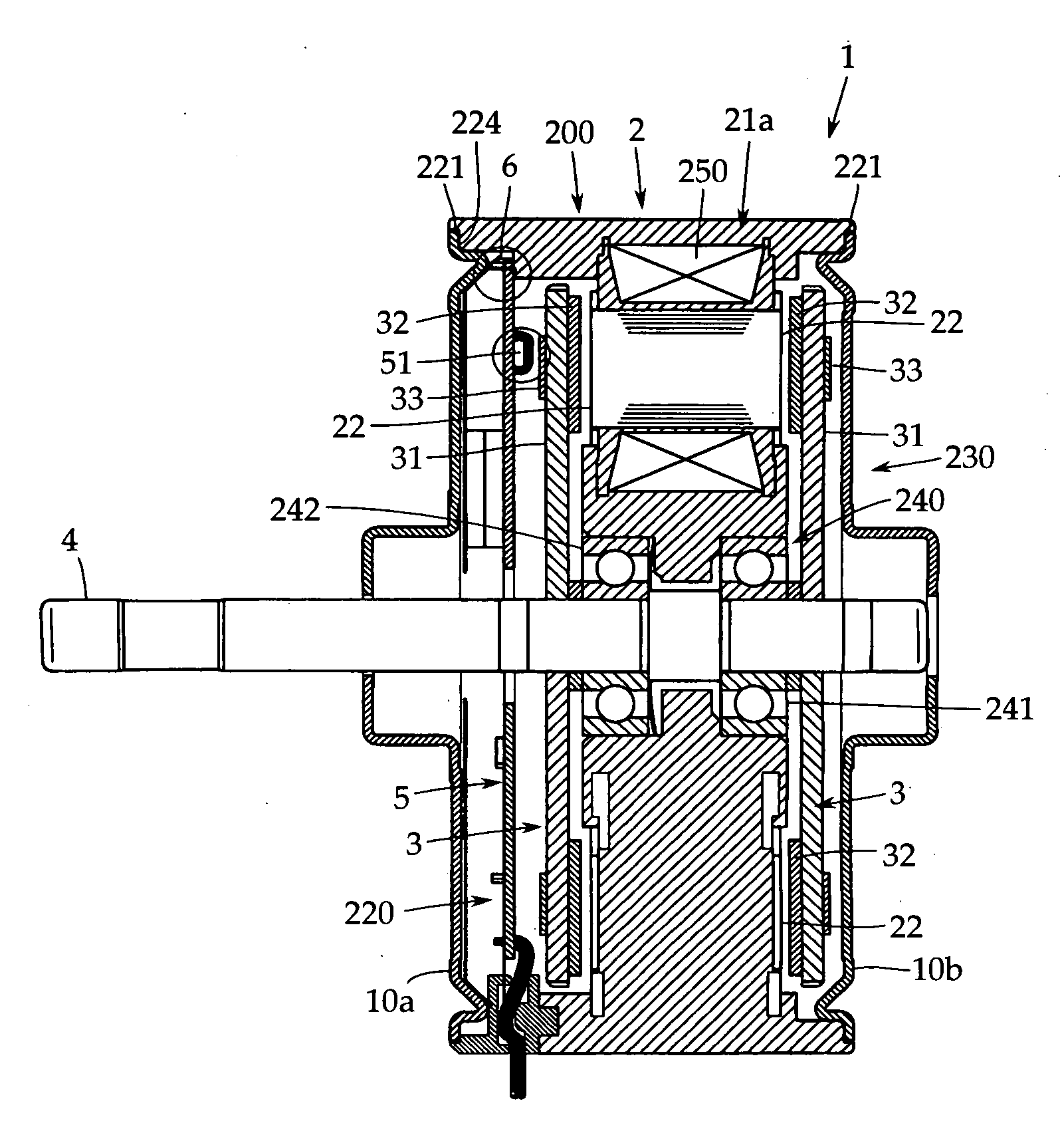
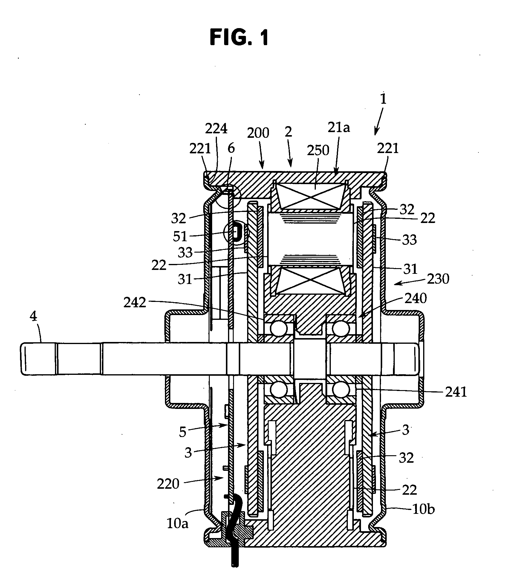
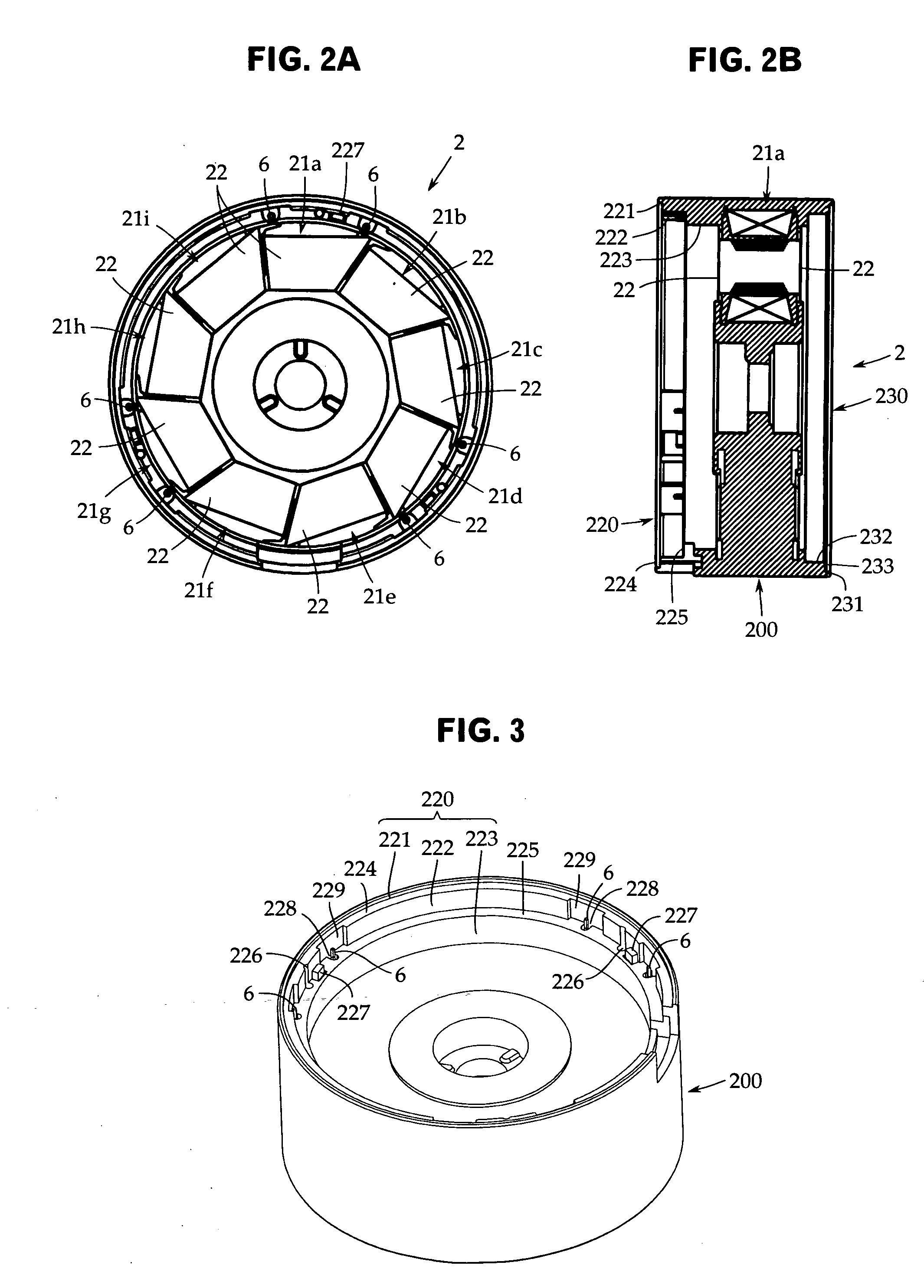
[0047] An embodiment of the present invention will now be described with reference to the accompanying drawings. The present invention is not limited to this embodiment. FIG. 1 is a sectional view of an essential portion of an axial air-gap electric motor in accordance with one embodiment of the present invention. FIGS. 2A and 2B are front and side views of a stator, respectively, and FIG. 3 is a perspective view of the stator.

[0048] This axial air-gap electric motor 1 has a stator 2 embedded in a resin compact 200 and a pair of rotors 3 arranged so as to face to both side surfaces of the stator 2 with a predetermined air gap being provided. The rotors 3 are fixed coaxially on a rotor output shaft 4 for delivering a rotational driving force.

[0049] The stator 2 is formed in a ring shape with the axis line of the rotor output shaft 4 being the center, and is integrally molded together with the resin compact 200 by insert molding. At both ends of the resin compact 200, lid members 10...


PUM

PropertyMeasurementUnit
Heightaaaaaaaaaa
Distanceaaaaaaaaaa

Abstract

In an axial air-gap electronic motor in which a stator is formed by a plurality of core members, the manpower for assembling the core member is reduced, and the motor is assembled in a shorter period of time. A hook portion 320, which is a first connecting means, is projectingly provided at one end in the circumferential direction of a flange portion 310 of each of the core members 21a to 21i, and a columnar locking shaft 330 to which the hook portion 320 is locked is provided at the other end in the circumferential direction of the flange portion 310, by which the core members 21a to 21i are connected to each other.

Description

TECHNICAL FIELD [0001] The present invention relates to an axial air-gap electronic motor in which a rotor and a stator are arranged so as to face to each other along the axis line direction of a rotor output shaft. More particularly, it relates to an axial air-gap electronic motor that requires less manpower for parts and is capable of being assembled easily in a short period of time. BACKGROUND ART [0002] As shown, for example, in Patent Document 1 (Japanese Patent Application Publication No. 2004-282989), an axial air-gap electronic motor is an electronic motor in which a rotor is arranged on one side surface or both side surfaces of a stator with a predetermined air gap being provided therebetween, and is characterized in that the thickness in the rotating shaft direction can be decreased, namely, the motor can be made flat as compared with a radial gap electronic motor of, for example, an inner rotor type. [0003] The axial air-gap electronic motor described in Patent Document 1...

Claims


Application Information

Patent Timeline
IPC IPC(8): H02K1/00
CPCH02K3/524H02K11/0073Y10T29/49009H02K2211/03H02K21/24H02K11/33H02K1/12H02K3/32
Inventor MATSUZAKI, HIROKAZUHORIUCHI, YOSHIYASUKOJIMA, TOMONORIYAMADA, MASAKI
Owner FUJITSU GENERAL LTD
Why Eureka
Try Eureka