

Electrophotographic photoreceptor, and image forming method and apparatus using the same
- Summary
- Abstract
- Description
- Claims
- Application Information
AI Technical Summary
Benefits of technology
Problems solved by technology
Method used
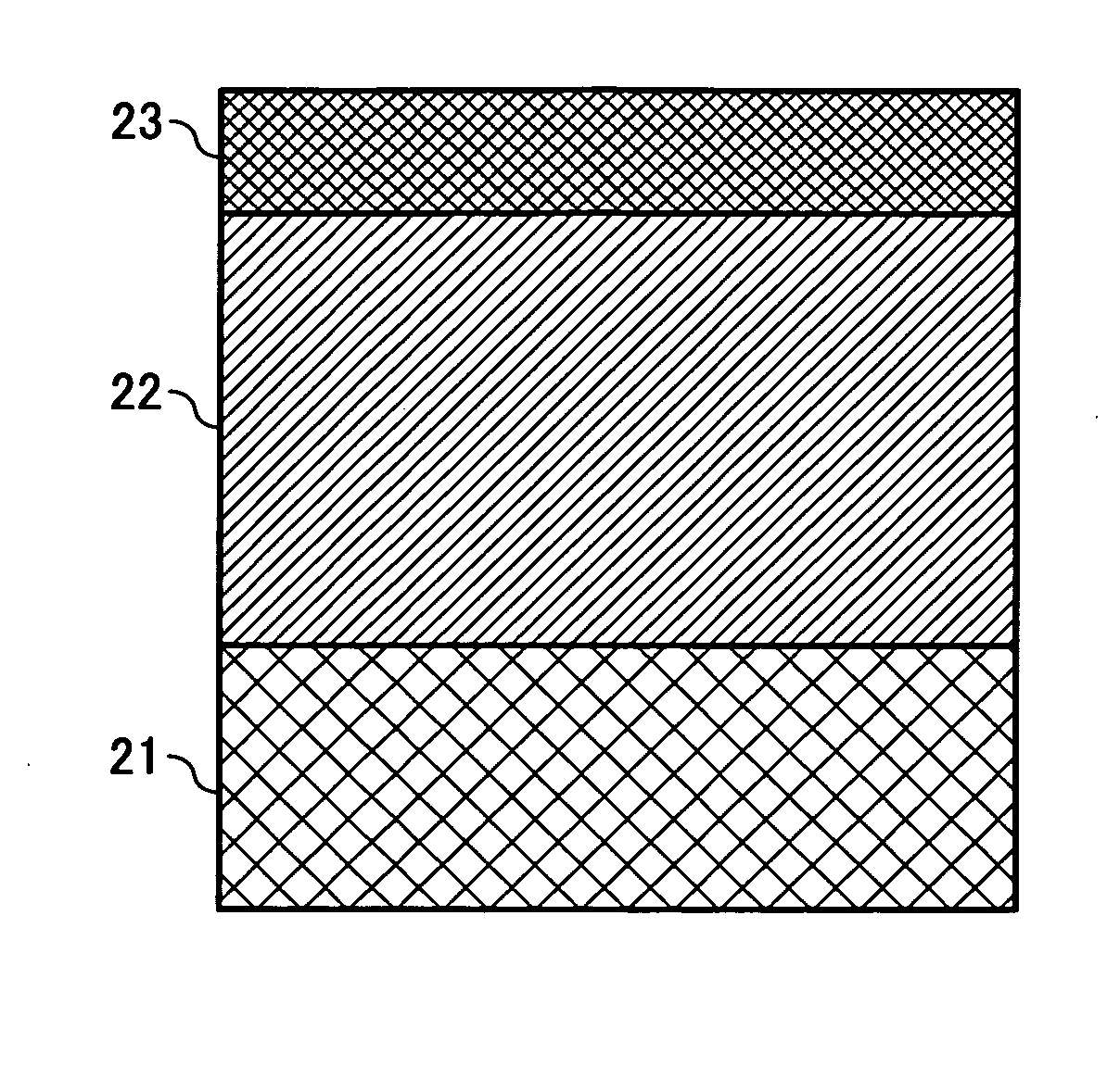
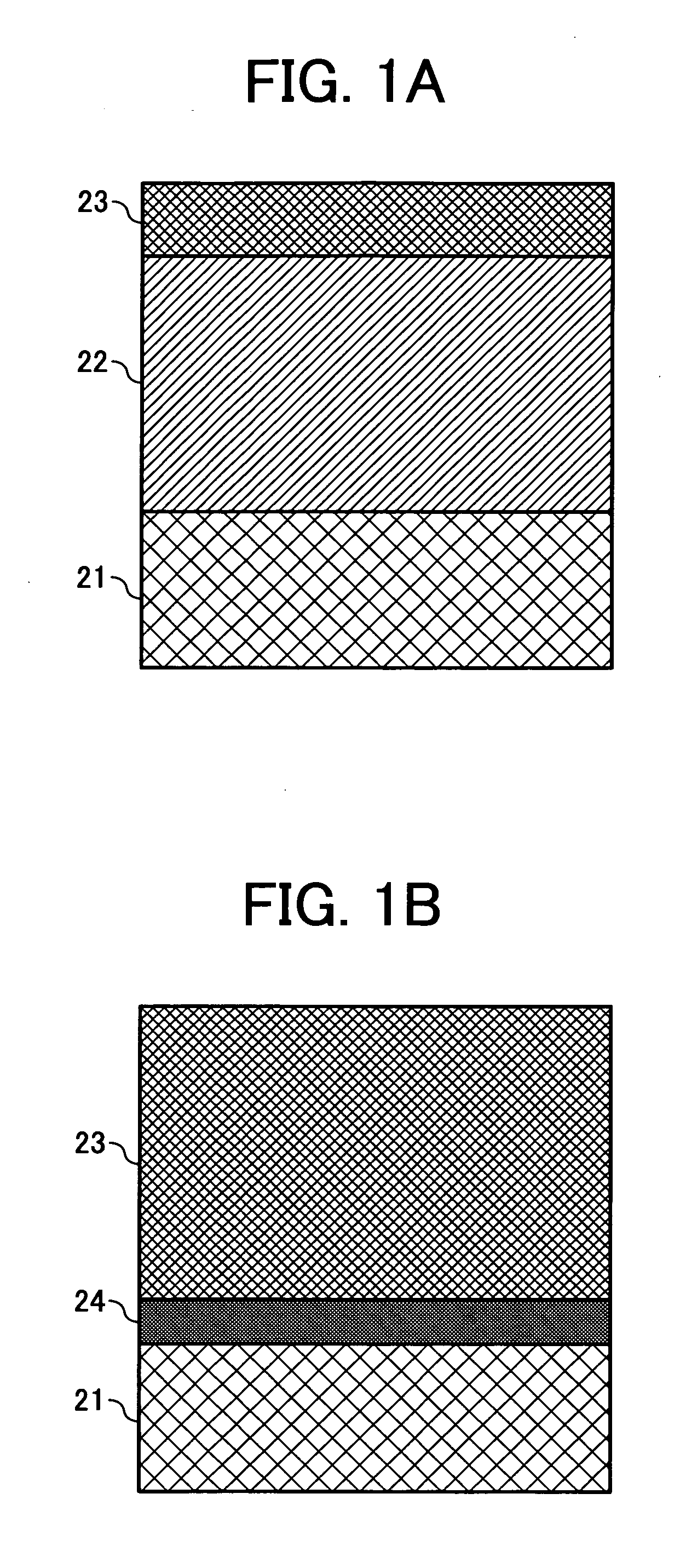
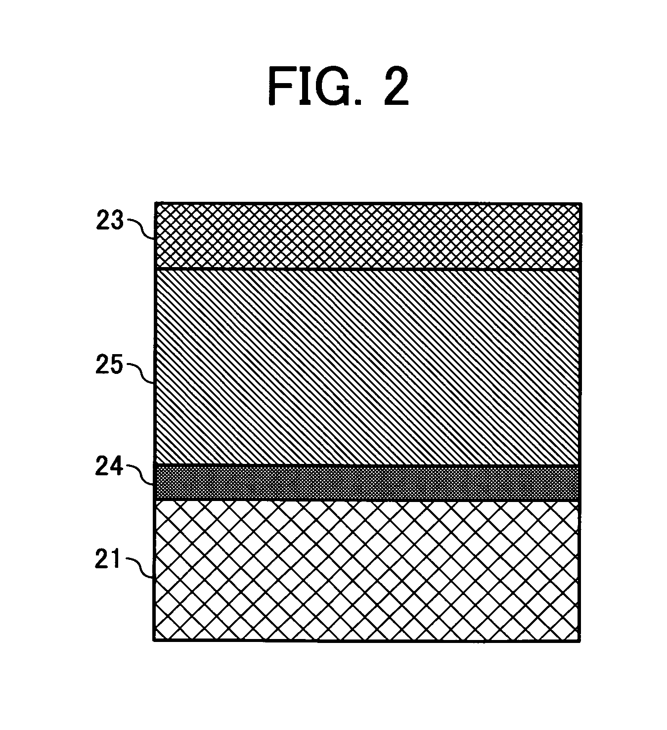
Image

Examples
synthesis example 1
[0299]The radically polymerizable compound having formula B-1-1 was synthesized as follows.
[0300]Specifically, 6 g (0.0224 mol) of 1,1-bis(4-hydroxyphenyl)cyclohexane (B1586 from Tokyo Kaei Kogyo Co., Ltd.) was dissolved in 70 ml of tetrahydrofuran. An aqueous solution of sodium hydroxide, which had been prepared by dissolving 3.76 g of sodium hydroxide in 32 ml of water, was dropped in the above-prepared solution under nitrogen gas flow. After the mixture was cooled to 2° C., 8.26 g (0.0456 mol) of acryl chloride was added thereto over 30 minutes. The mixture was agitated for 5 hours in a temperature range of from 2 to 5° C. to complete the reaction. The reaction product was fed into water to cause a precipitate, followed by filtering. The thus prepared crude product (white powder) was washed with water, followed by filtering. This washing operation was repeated several times. The crude product was then subjected to a column chromatographic treatment using a silica gel as an absorb...
synthesis example 2
[0303]The radically polymerizable compound having formula B-2-4 was synthesized as follows.
[0304]Specifically, 6 g (0.0137 mol) of 9,9-bis[4-(2-hydroxyethoxy)phenyl]fluorene (F0447 from Tokyo Kaei Kogyo Co., Ltd.) was dissolved in 70 ml of dimethylacetamide. After the mixture was cooled to 3° C., 6.95 g (0.0548 mol) of 3-chloropropionylchloride was added thereto under a nitrogen gas flow. The mixture was agitated for 3.5 hours at room temperature. Next, 11.08 g of triethylamine was added thereto over 40 minutes at room temperature under a nitrogen gas flow. The mixture was agitated for 4 ours at 60° C. to complete the reaction. The reaction product was fed into water, and the mixture was subjected to an extraction treatment using ethyl acetate. The thus extracted liquid was repeatedly washed with water. After the solvent was removed from the extracted liquid, the reaction product was refined by a column chromatographic treatment using a silica gel as an absorbent, and a mixture solv...
synthesis example 3
[0308]The radically polymerizable compound having formula C-1-1 was synthesized as follows.
(1) Synthesis of Intermediate Compound having the Following Formula
[0309]
[0310]At first, 9.83 g (0.0366 mol) of 1,1-bis(4-hydroxyphenyl)cyclohexane (B1568 from Tokyo Kaei Kogyo Co., Ltd.) and 12.06 g (0.0806 mol) of glycidyl methacrylate were dissolved in 50 ml of toluene. After 0.3 ml of triethylamine was added thereto, the mixture was agitated for 9 hours at 95° C. under an argon gas flow. Next, 37 ml of a 10% aqueous solution of sodium hydroxide and 30 ml of toluene were added thereto at room temperature. The mixture was agitated for 6 hours at 92° C. to complete the reaction. The reaction product was neutralized with hydrochloric acid to cause a precipitate. The thus precipitated crystal was separated by filtering, followed by washing with water. The crystal was refined by a column chromatographic treatment using a silica gel as an absorbent, and a mixture solvent of ethyl acetate / tetrahyd...
PUM
| Property | Measurement | Unit |
|---|---|---|
| Mass | aaaaa | aaaaa |
| Fraction | aaaaa | aaaaa |
| Fraction | aaaaa | aaaaa |
Abstract
Description
Claims
Application Information