Liquid spray shield for liquid-cooled alternators

Inactive Publication Date: 2006-08-03
REMY INT
View PDF10 Cites 17 Cited by
  • Summary
  • Abstract
  • Description
  • Claims
  • Application Information

AI Technical Summary

Benefits of technology

[0008] The above discussed and other drawbacks and deficiencies are overcome or alleviated by the placement of a metal shield behind a rubber seal lip of an oil seal for the rotor shaft thus preventing high velocity liquid spray from directly contacting the seal. More specifically, the shield is placed between an outermost bearing and the oil seal. The shield prevents high velocity liquid cooling spray, such as oil spray, emitted from the bearing from contacting the rubber seal lip. This design allows both radial misalignment of the placement of the seal and some eccentricity of the seal contact surface of the shaft.
[0009] In an exemplary embodiment, a spray shield for a bearing assembly of an electrical machine includes a shield disposed intermediate an outermost bearing and rubber seal lip of a seal. The shield has an aperture allowing a rotor shaft to extend therethrough. The seal is configured to at least one of reduce hydraulic pressure at the seal lip and reduce a liquid leaking through the seal lip.
[0010] In another embodiment, a liquid-cooled rotating electrical machine is disclosed. The electrical machine includes: a rotor having a longitudinal axis; a stator surrounding the rotor; one or more frames rotatably supporting the rotor, at least one of the frames having a hub with a core with an opening for receiving a bearing mounting the rotor with the hub; and a spray shield disposed intermediate the bearing and a rubber seal lip of a seal. The shield has an aperture allowing a rotor shaft to extend therethrough. The seal is configured to at least one of reduce hydraulic pressure at the seal lip and reduce a liquid leaking through the seal lip.
[0011] In yet another embodiment, a method to suppress oil spray generated in a brush or brushless type rotor of a wound-field electrical machine is disclosed. The method includes disposing a metallic shield intermediate an outermost bearing and rubber seal lip of an oil seal. The shield has an aperture allowing a rotor shaft to extend therethrough. The seal is configured to at least one of reduce hydraulic pressure at the seal lip and reduce a liquid leaking through the seal lip

Problems solved by technology

However, shaft seals leak oil, creating negative cosmetic conditions and, if leaking at a high enough rate, may cause the vehicle operator to be subjected to fines from local, state or federal government agencies.
Furthermore, oil spray from a rotating bearing can increase the hydraulic pressure at the rubber seal lip of the input shaft seal and increase leakage of oil through the seal.

Method used


Image

  • Liquid spray shield for liquid-cooled alternators
  • Liquid spray shield for liquid-cooled alternators
  • Liquid spray shield for liquid-cooled alternators

Examples


Embodiment Construction

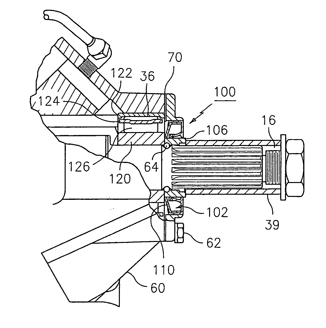
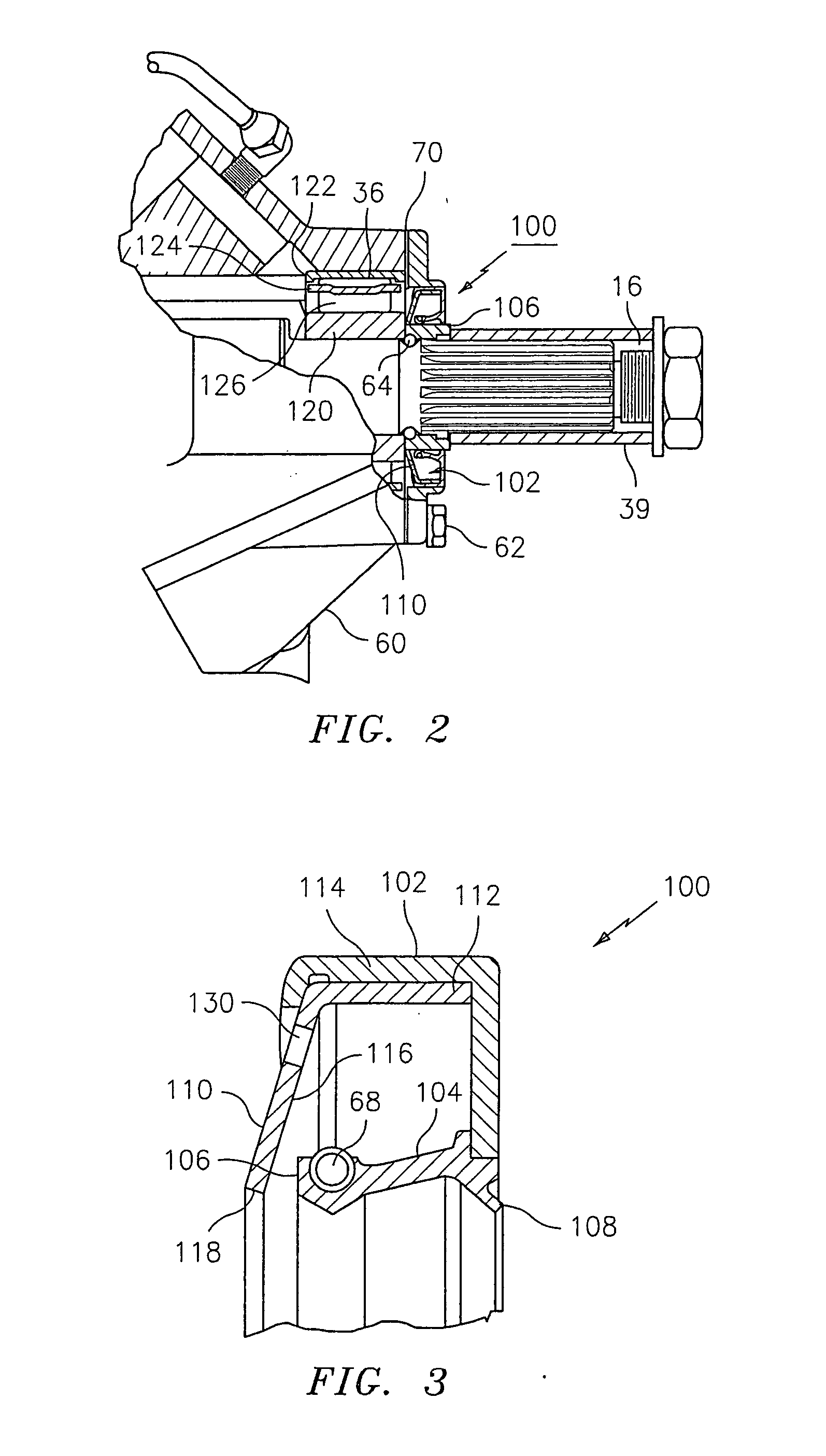
[0021] This disclosure relates to a method and apparatus for reducing hydraulic pressure and liquid spray at the rubber lip of the input shaft seal while reducing or eliminating oil leaks through the seal. The present disclosure provides an improvement over previous designs in that it allows both radial misalignment of the placement of the seal and some eccentricity of the seal contact surface of the shaft.

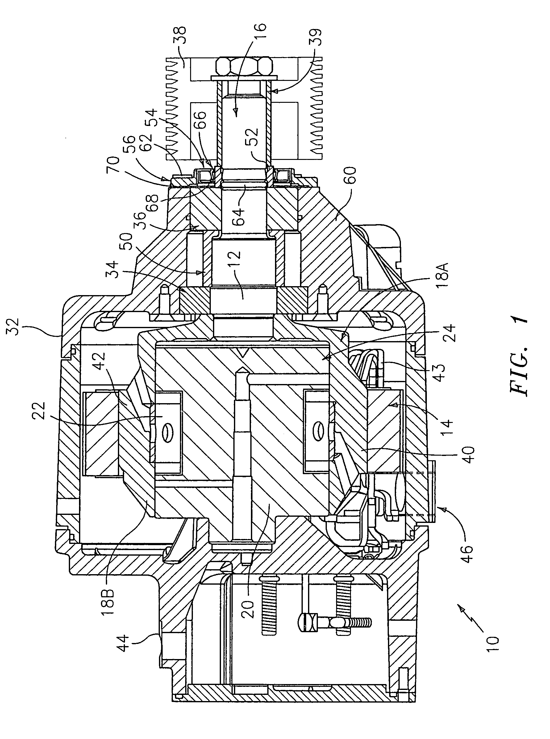
[0022] Referring now toFIG. 1, an alternator 10 has a rotor assembly generally designated by the reference numeral 12 and stator assembly generally designated by the reference numeral 14. The rotor assembly 12 includes a shaft 16 supporting all rotating magnetic circuit structures thereof including conventional pole-members or segments 18A and 18B, and possibly a rotor core 20 and field coil 22 wound upon bobbin 24. Each segment 18A and 18B has P / 2 claw poles where P is an even number and representative of the total number of poles. Additionally, all other non-magnetic circuit ro...


PUM


Abstract

A spray shield for a bearing assembly of an electrical machine includes a shield disposed intermediate an outermost bearing and rubber seal lip of a seal. The shield has an aperture allowing a rotor shaft to extend therethrough. The seal is configured to at least one of reduce hydraulic pressure at the seal lip and reduce a liquid leaking through the seal lip.

Description

TECHNICAL FIELD [0001] This application relates generally to the field of liquid spray shields in rotating electrical machines. More specifically, this application relates to liquid spray shields in rotating electrical machines, especially dynamoelectric machines including oil-cooled alternators (generators), such as those found in large city busses and coaches. BACKGROUND [0002] Rotating electrical machines such as vehicle alternators (dynamoelectric machines) (also commonly referred to as “generators”) having a stator secured within the housing of the machine and a rotor assembly that extends axially through the motor or generator are well known. The housing often includes two or more spaced apart frames which provide the main structural elements of the alternator. The frame closest to a pulley, which powers the alternator via a belt drive is commonly referred to as the drive end frame. The opposite frame is commonly referred to as the slip ring end frame. The frames support the r...

Claims


Application Information

Patent Timeline
IPC IPC(8): H02K5/15
CPCH02K5/124H02K9/19
Inventor EDRINGTON, SAMUEL R.
Owner REMY INT
Why Eureka
Try Eureka