Load distributing method

a load distribution and load technology, applied in the field of communication systems, can solve the problem of rate control of the transfer rate between nodes, and achieve the effect of reducing multiplexing efficiency, avoiding multiplexing efficiency, and effectively using path resources

Active Publication Date: 2007-01-04
NEC CORP
View PDF54 Cites 46 Cited by
  • Summary
  • Abstract
  • Description
  • Claims
  • Application Information

AI Technical Summary

Benefits of technology

[0076] According to the present invention, the path status information obtained from a reception side is applied to data (packets) transmitted in past, to which the status information is validated. By reflecting the result to predict the data (packets) to be transmitted, the arrival time or reception completion time of the data is predicted. This method can predict with higher accuracy, compared with the conventional art. The reason is that, in the conventional art, the path information obtained from the reception side is applied only to data (packets) to be transmitted to predict the arrival time or reception completion time.
[0077] According to the present invention, in order to transfer data between two nodes, each which can select plural paths, the path status information obtained from the reception side is applied to data transmitted in past which validates the information. The result is reflected to predict data to be transmitted and the data arrival time or the reception completion time is predicted. Since the path selection is performed based on the prediction, a suitable path is selected, without selecting an erroneous path due to a prediction error. Thus the problem that the multiplexing efficiency decreases can be avoided.
[0078] According to the present invention, in order to transfer between two nodes, which can select plural paths, the path resources can be effectively used even when the performance of each path dynamically changes and a large return delay, not negligible, exists, compared with the time constant.

Problems solved by technology

However, the problem is that when the rates between paths are in imbalance, the transfer rate between nodes is rate-controlled to the slowest path.

Method used


Image

  • Load distributing method
  • Load distributing method
  • Load distributing method

Examples


Embodiment Construction

[0114] A best mode for carrying out the present invention will be explained below.

[0115] It is assumed that an aspect of the present invention is applied to the technique combining plural paths, of which the rate as well as the delay vary dynamically, particularly, paths including radio links to construct one logical path. Inverse multiplexing will be explained below as an example of a technique of constructing one logical path through a combination of plural paths.

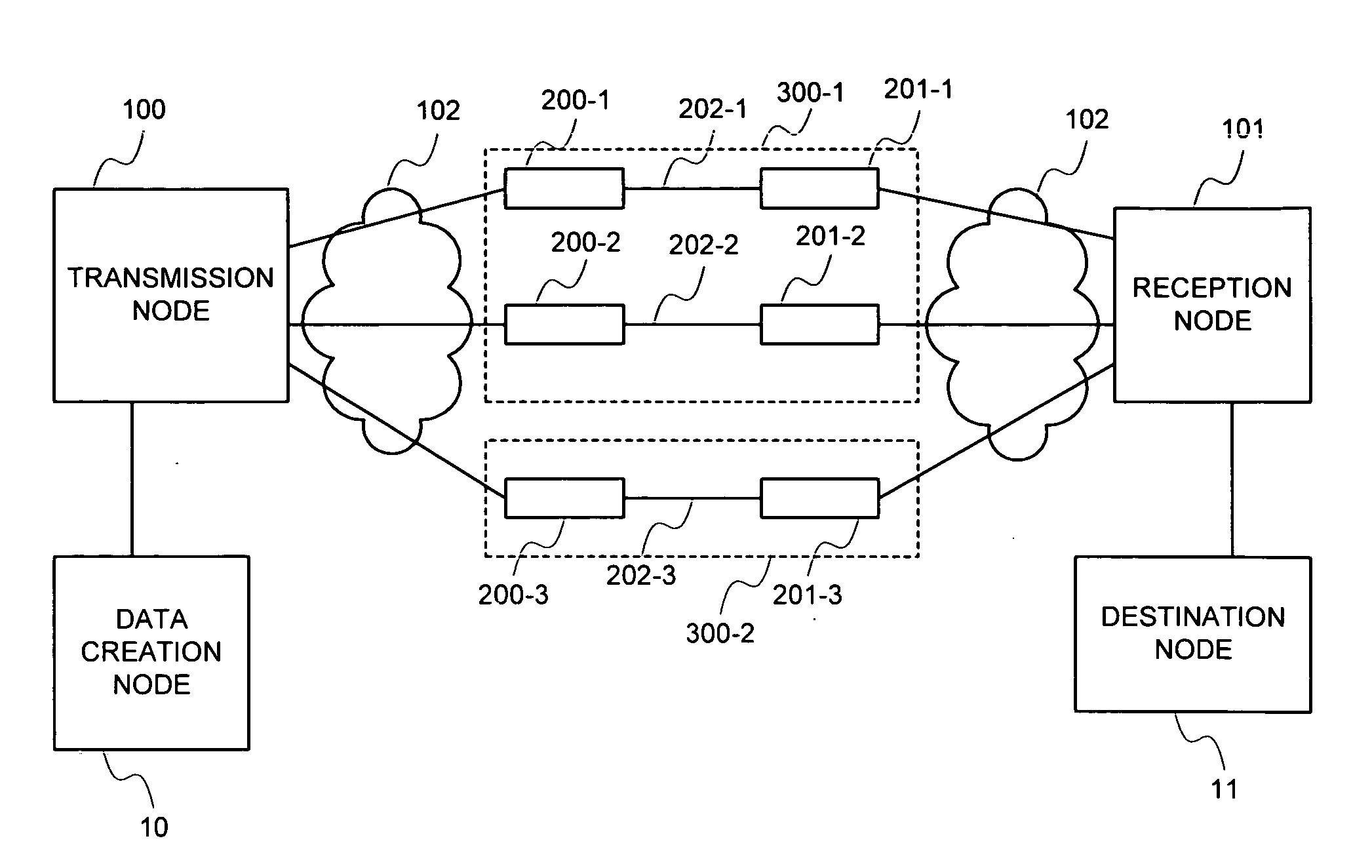
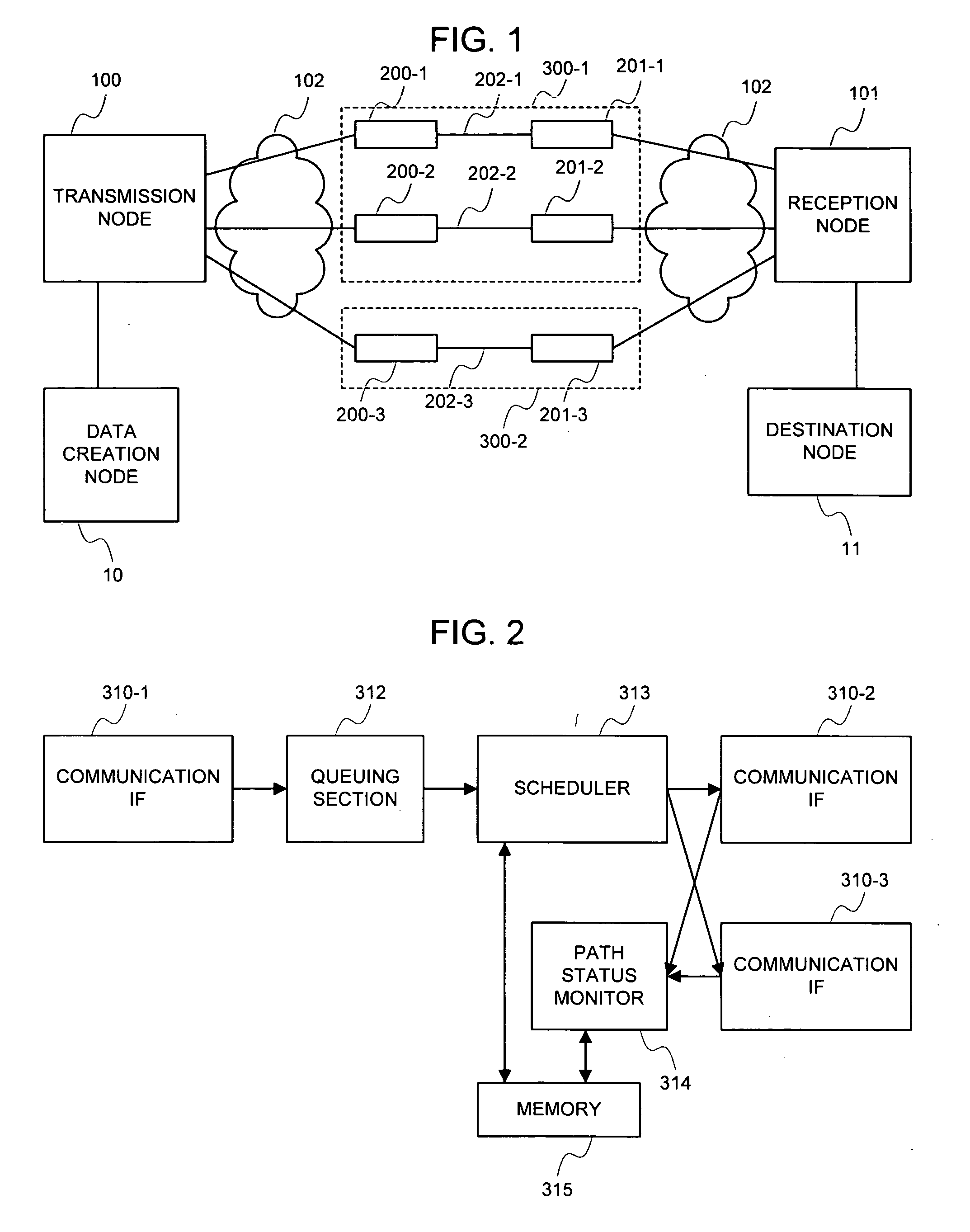
[0116]FIG. 1 shows a structural example of the present embodiment.

[0117] Referring to FIG. 1, a transmission node 100 and a reception node 101, each implementing inverse multiplexing, exist in a path between a data creation node 10 and a destination node 11. There are three paths between the transmission node 100 and the reception node 101. Radio links 202-1 to 202-3 are respectively in communication paths between radio transmission means 200-1 to 200-3 and radio reception means 201-1 to 201-3. Three paths are shown in...


PUM


Abstract

When path status information is updated, the time at which the update is effective is recorded. A packet arrival time in each path is predicted based on new status information and data transmission history after the effective time. The packet is transmitted to the path that provides a fastest packet arrival time. This reflects the path status available from the reception side on the data transmitted in past, so that an actual data arrival time, an arrival time close to a reception completion time, or a reception completion time can be predicted.

Description

TECHNICAL FIELD [0001] The present invention relates to a communication system between two nodes usable plural communication paths. Particularly, the present invention relates to a technique of distributing the load between paths by a transmission node. BACKGROUND OF THE RELATED ART [0002] In plural paths between two nodes, the transmission side dispersively inputs traffics to respective paths and the reception side reintegrates them from the respective paths. Thus, a higher transfer rate can be obtained in principle, compared with the case where a single path is used. This mechanism relates to a technique of combining paths to construct one logical path. Typically, Inverse Multiplexing is cited, which is utilized to obtain a logical broad band line from plural low rate links. As applications to data communications, there are multiplexing of ATM line and Multilink PPP being a multiplex protocol for PPP links. [0003] As a traffic distribution scheme, typified by Inverse Multiplexing,...

Claims


Application Information

Patent Timeline
Patent Type & Authority Applications(United States)
IPC IPC(8): H04J3/14H04L45/24H04L45/121
CPCH04L12/56H04L43/0858H04L43/0864H04L43/087H04L47/283H04L43/0894H04L45/00H04L45/22H04L43/0882H04L47/122H04L45/30
Inventor NAKATA, TSUNEONOGUCHI, YUUSUKE
Owner NEC CORP
Why Eureka
Try Eureka