Model-driven service creation and management

Active Publication Date: 2007-01-04
NYTELL SOFTWARE LLC
View PDF9 Cites 6 Cited by
  • Summary
  • Abstract
  • Description
  • Claims
  • Application Information

AI Technical Summary

Benefits of technology

[0005] In yet another embodiment, views of the service model from the perspective of an individual OSS subsystem are then published at a Service Hub for use in configuring new services. The service model can then be used by OSS vendors to present interfaces for service deployment, can be used by the service hub to deploy the service across multiple OSS for functionality such as provisioning, assurance and billing, as well as sub-service components that may be provided by different vendors or OSS. When a request for service arrives at a subsystem in the network, such as an ordering subsystem, that subsystem will illustratively request a view of the service from the Service Hub. This view is representative of the functionality that the requesting subsystem must provide for the new service as well as the interfaces and attributes common between the requesting subsystem and other network components with interfaces to the requesting subsystem. In accordance with this embodiment, in response to this request, the Service Hub will transmit the respective view to the subsystem. The requesting subsystem then interprets this view to define its actions with respect to the new service and uses this view to transmit values of attributes that are defined to be communicated between the requesting subsystem and other network components. Accordingly, adding new services may not require any changes to the underlying software of the subsystems and, as a result, services may be introduced with a lower cost and shorter delay than traditionally associated with the definition, development, deployment and testing of those services.

Problems solved by technology

While the prior methods of introducing new services into networks are advantageous in many aspects, they are also disadvantageous in some regards.
Thus, the process of implementing a new service was a costly and time intensive process that resulted in delays in the introduction of these new services.

Method used


Image

  • Model-driven service creation and management
  • Model-driven service creation and management
  • Model-driven service creation and management

Examples


Embodiment Construction

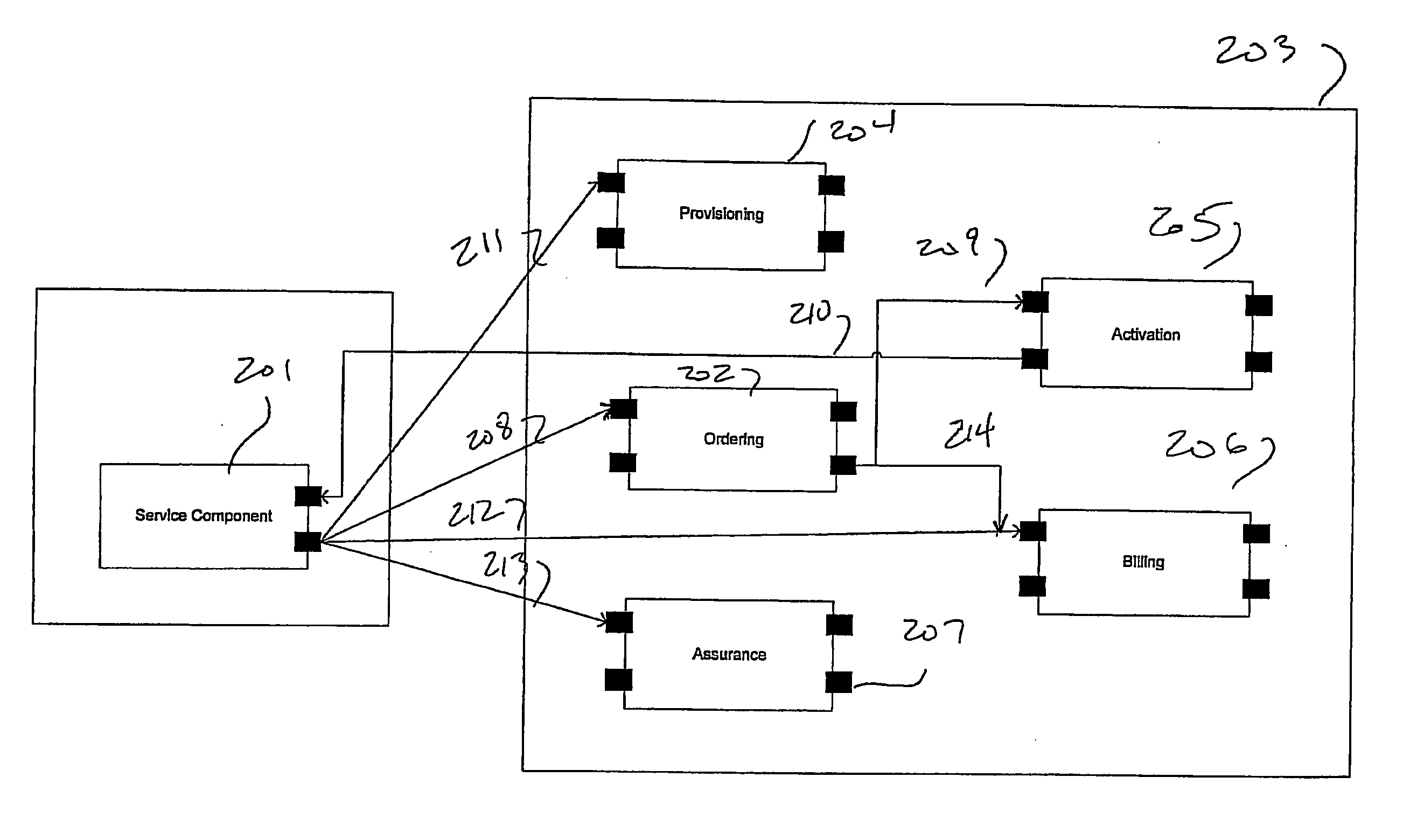
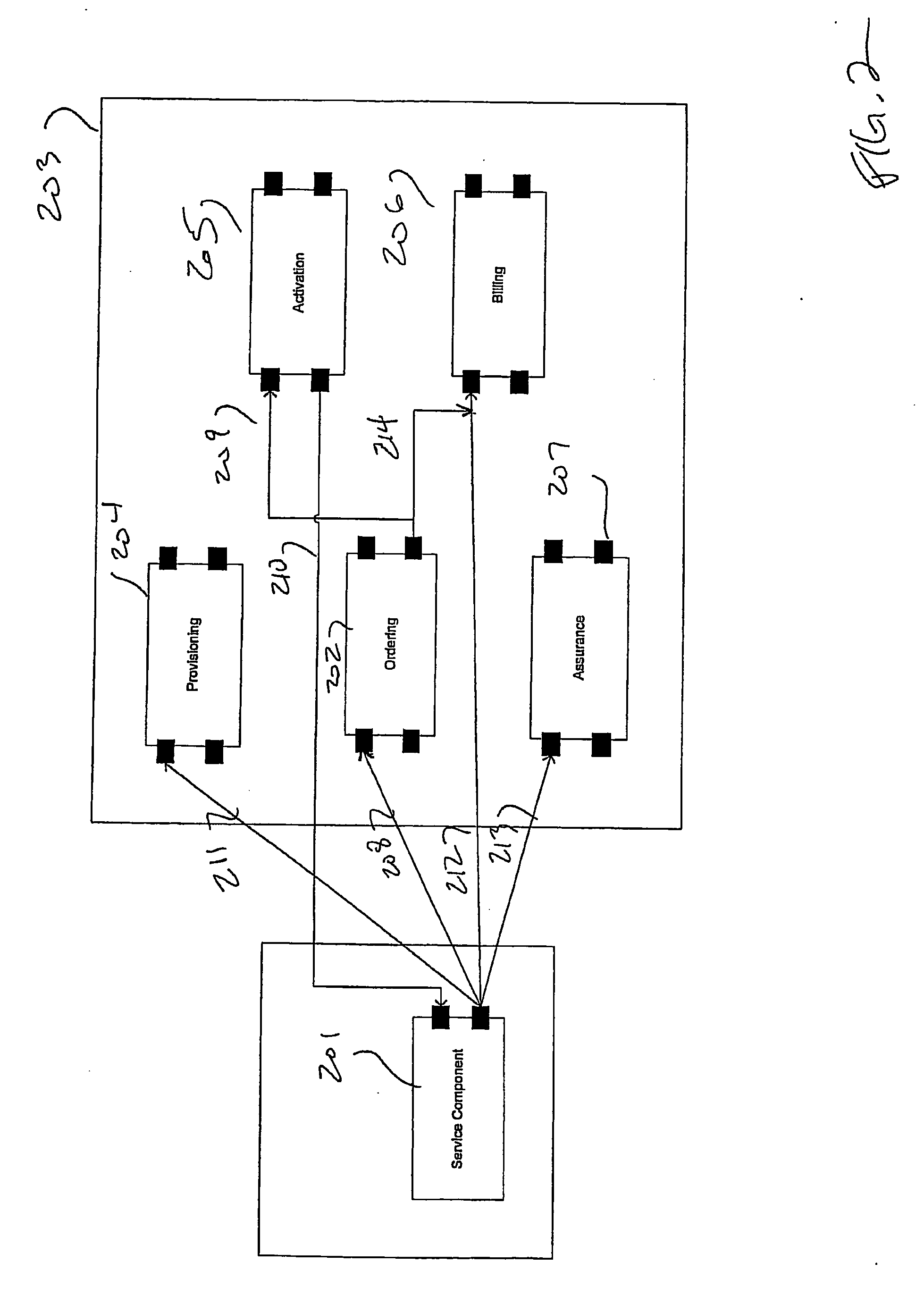
[0015] A telecommunication system is generally composed of a set of operational subsystems, each of which implements some portion of the overall communication system service logic. Each operational subsystem consists of a set of input and output interfaces connected by internal logic defining the subsystem's operation. Interfaces on a subsystem enable the respective subsystem to receive and provide data from or to, respectively, an associated Operational Support System (OSS) environment, as discussed above. For example, a call agent or softswitch component of a voice over IP (VoIP) service may require some subset of service order data from an order management system in order to activate service for a subscriber. It may also need to provide usage data of individual subscribers to an ordering system for billing and auditing purposes.

[0016] Such a component view of services can be extended to OSS systems in that the subsystems of an OSS can be treated as distributed subsystems that co...


PUM


Abstract

A method and apparatus for implementing new services is disclosed whereby a model of the system implementing the new service is created by a function referred to herein as a Service Designer and then different views of that service from the perspective of an individual OSS subsystem is published at a Service Hub for use in configuring new services. When a request for service arrives at a subsystem in the network, such as an ordering system, that subsystem will illustratively request a view of the service from the Service Hub. This view is representative of the interfaces and attributes common between the requesting subsystem and other network components; with interfaces to the requesting subsystem. The requesting subsystem then uses this view to transmit values of attributes that are defined to be communicated between the requesting subsystem other network components.

Description

BACKGROUND OF THE INVENTION [0001] As complex converged telecommunication networks designed to provide a wide range of services to customers become more prevalent, the need for integrating new services in a timely manner becomes increasingly important. Operations support systems (OSSs) in telecommunication systems have many different elements that require frequent updates and improvements when new services are introduced to customers. Such OSS systems typically include order management, design and engineering, carrier interconnection, service provisioning, inventory, service activation, billing, customer care and service assurance subsystems. These subsystems are able to interact with each other and with various network elements and also must be able to accept input from and provide information to external elements, such as sales, engineering and technician personnel. Accordingly, such systems are complex and require careful configuration control. [0002] OSS systems are typically li...

Claims


Application Information

Patent Timeline
IPC IPC(8): H04L12/26H04J1/16H04J3/14
CPCH04L41/0806H04L67/16H04L41/5054H04L67/51
Inventor WULLERT, JOHN R. IICOCHINWALA, MUNIRSHIM, HYONG SOP
Owner NYTELL SOFTWARE LLC
Why Eureka
Try Eureka