
Patient table for an X-ray system

a patient table and x-ray technology, applied in the field of patient tables for x-ray systems, can solve the problems of geometric enlargement of images, insufficient proximity to detectors, and geometric limitation of the region to be examined,

Inactive Publication Date: 2007-01-04
SIEMENS HEALTHCARE GMBH
View PDF27 Cites 8 Cited by
  • Summary
  • Abstract
  • Description
  • Claims
  • Application Information

AI Technical Summary

Benefits of technology

[0009] With the x-ray systems of the prior art, it is the object of the invention to provide a measure, by means of which the x-ray system retains its flexible applicability, with the recording in particular being more easily configurable in the case of an upright patient table.
[0013] In contrast to a complete table top, a small module can be easily removed; however, the complete table top need not always be removed, and it is instead sufficient for the said module to release the upper body of the patient or at least the head of the patient. A module which is located in particular in the region of the patient's head (head module) is easy to carry and its removal is thus not a problem even for persons of limited strength.
[0014] The two modules are preferably interlocking and locked. This increases the stability of the patient table. By way of example, the locking of the module can be unlocked after actuating at least one bolt, such as for instance a damping spring bolt. Such a spring bolt prevents a module from being unintentionally removed.
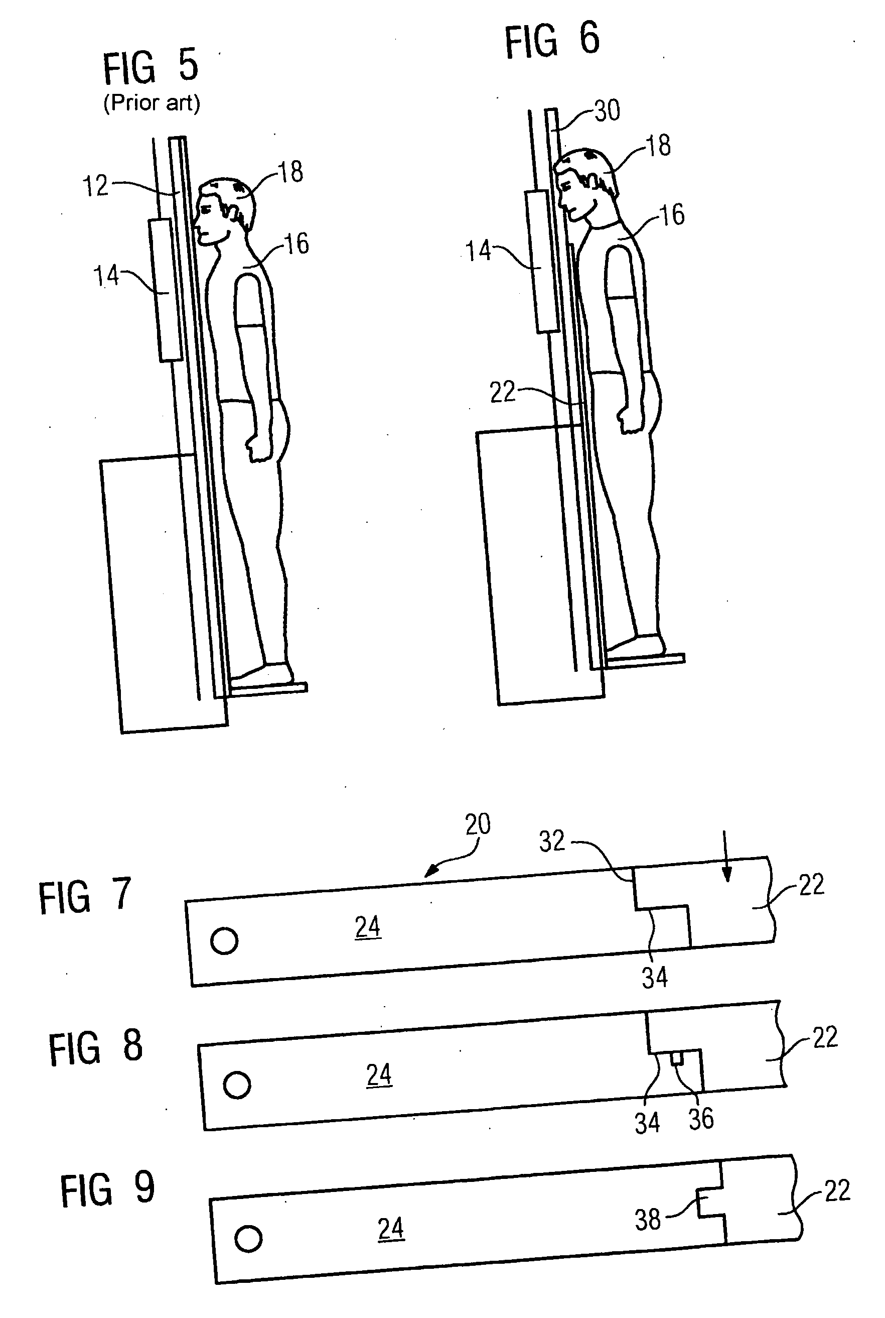
[0015] The profiles of the two modules are also designed to interlock along the thickness direction of the table top, i.e. in the direction of the height of the table top (with a horizontal table top). This should not only increase the stability, but also essentially inhibit the flow rate of fluid. In addition, provision is made in the region of the interlocking in a module profile for a groove or notch for receiving fluid seeping through the region. In this way, the x-ray detector is hereby particularly protected against the patient's bodily fluids, which can occasionally escape during some treatments.
[0020] Occasionally the detector is not located directly in the region of the head or, if necessary, the lungs to be imaged. Provision can be made for the x-ray detector to be moveable with shortened table top lengths. By way of example, the movement of the x-ray detector can be triggered by removing an x-ray module or by shortening the roller blind-type table top. The x-ray detector can then be moved behind the (remaining) table, such that at least one sub-area of the x-ray detector can be directly radiated by the x-ray emitter (after x-raying the patient) and the table top is no longer located in the corresponding radiation path to the x-ray detector. This measure allows a remaining interference to be stopped by means of the remaining table top.
[0023] The above mentioned triggering of the bolt or movement of the roller blind type patient table as a function of a tilting angle of the patient table allows the patient table to be shortened only when it is upright, in other words for a lung recording for instance, whereas when the patient table is in a horizontal position, the corresponding functionality to shorten the patient table can be electronically blocked (by means of a corresponding programming of the data processing system etc.), so that the patient table is not shortened by mistake.

Problems solved by technology

In the prior art, the patient cannot get sufficiently close to the detector, as a result of the table top located in the radiation path, which results in a geometric enlargement of the image and a geometric limitation of the region to be examined.
By way of example, the quality of the lung recordings is hereby restricted in that the shoulder regions (tips of the lungs) are not imaged sufficiently well.
The positioning of the patient to the detector is complicated since it is not possible to fix him / her to the detector housing or to position him / her suitably.
This solution is complex and requires more space, thereby rendering it expensive.
Since this is an extremely heavy load, its removal is very complex.

Method used


Image

  • Patient table for an X-ray system
  • Patient table for an X-ray system
  • Patient table for an X-ray system

Examples


Embodiment Construction

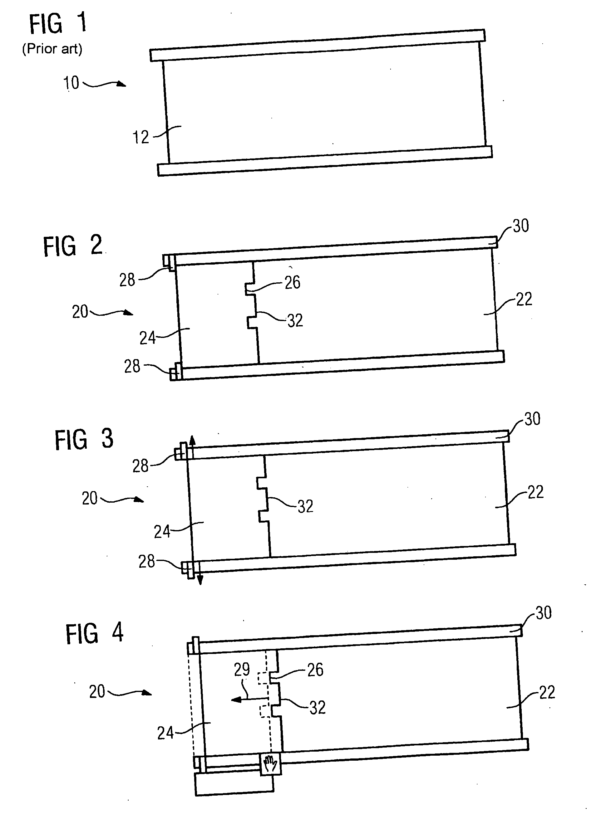
[0032]FIG. 1 shows a patient table 10 of the prior art for an x-ray system with a stable, fixed table top 12 comprising one piece.

[0033] In the prior art, the table top 12 is then in the way if the patient is to be recorded in an upright position. This is illustrated in FIG. 5. When the patient table 12 is in an upright position, the patient table interferes in the radiation path (from the x-ray emitter (not shown)) to the x-ray detector 14. It would be desirable for a patient 16 to move his / her head 18 as close as possible to the x-ray detector 14. Compared with the horizontal function, the table 12 has completely lost its function and in the prior art is frequently completely removed. Such a table is however very heavy.

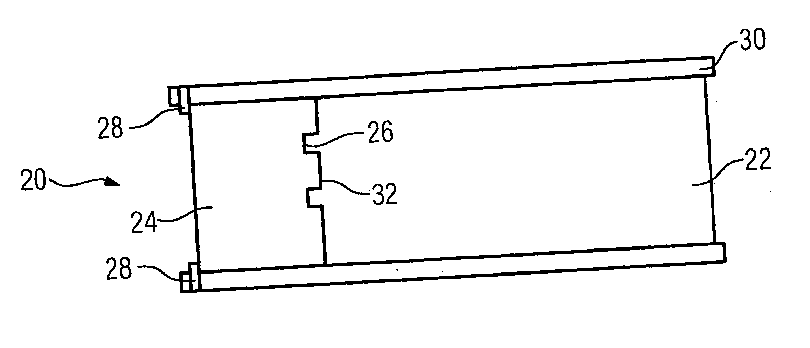
[0034] The invention provides a patient table 20, as shown in FIG. 2. The patient table 20 comprises two modules, a main table module 22 and a head module 24. The two modules interlock at their juncture by means of teeth 26 and are locked.

[0035] Damping spring bo...


PUM


Abstract

The invention relates to a patient table (40) for an x-ray system with a table top, the length of which can be optionally varied. The table top can be of a modular design, or can comprise a plurality of table segments or slats (42) depending on the type of a shutter.

Description

CROSS REFERENCE TO RELATED APPLICATIONS [0001] This application claims priority of German application No. 10 2005 30 378.1 filed Jun. 29, 2005, which is incorporated by reference herein in its entirety. FIELD OF THE INVENTION [0002] The invention relates to a patient table for an x-ray system with a table top. BACKGROUND OF THE INVENTION [0003] X-ray systems are increasingly designed such that they cover as many clinical applications as possible with one device. Advantages of these types of universal and combined systems are the low costs and space requirements. [0004] Applications pertaining hereto are those in which the patient is not positioned on a patient table, but is instead standing and supported by the table. Examples for this are x-ray recordings of the lung. The patient table is then brought into an upright position. In the prior art, the patient cannot get sufficiently close to the detector, as a result of the table top located in the radiation path, which results in a g...

Claims


Application Information

Patent Timeline
Patent Type & Authority Applications(United States)
IPC IPC(8): A61B6/04
CPCA61B6/04
Inventor HORNIG, MATHIAS
Owner SIEMENS HEALTHCARE GMBH
Learn More