AI technical title is built by PatSnap AI team. It summarizes the technical point description of the patent document.
a technology of transition member and catheter, which is applied in the direction of stents, dilators, surgery, etc., can solve the problems of kinking at the joint, affecting the flexibility of the transition, and the hypertubing is often prone to kinking
Inactive Publication Date: 2007-01-04
BOSTON SCI SCIMED INC
View PDF99 Cites 8 Cited by
Summary
Abstract
Description
Claims
Application Information
AI Technical Summary
This helps you quickly interpret patents by identifying the three key elements:
Problems solved by technology
Method used
Benefits of technology
Benefits of technology
[0009] The present invention overcomes many of the disadvantages of the prior art by providing a transition member that transitions or varies the stiffness of a catheter from a stiffer more pushable proximal section to a more flexible and trackable distal section, while reducing kinkability in the transition. The transition member preferably has a spiral cut provided therein over at least a portion of its axial length to increase the flexibility of the transition member. The pitch of the spiral cut is varied to facilitate a gradual transition in flexibility along the catheter as supported by the transition member. It is contemplated that the transition member may be used in conjunction with all types of catheters including, but not limited to, single-operator-exchange type catheters, over-the wire type catheters, and / or fixed-wire type catheters.
[0011] The flexibility of the transition member preferably increases along its length. This can be accomplished by providing a spiral cut or the like which extends through the side wall of the transition member. The spiral cut provides flexibility to the transition member, and if the pitch of the spiral cut is changed over the length, can provide a relatively smooth transition in flexibility from the relatively stiff proximal section-to the relatively flexible distal section of the catheter while providing increased kink resistance. The transition member may be made from a stainless steel hypotube or other metallic tube, such as nitinol, an un-reinforced polymeric tube, a reinforced polymeric tube, or any other suitable material or element.
[0018] In a preferred embodiment, the transition member is secured to or proximate to the intermediate portion of the inner member and extends distally therefrom. To help secure the transition member to the inner member, the transition member may have a proximal portion sized so that the transition member can be friction fit over a portion of the tapered portion of the inner tube. An adhesive may also be used to secure the transition member to the intermediate portion of the inner tube. In a preferred embodiment adhesive is applied proximate the proximal end of the transition member only so that the transition member distal of the adhesive is free-floating. As discussed above, the transition member may engage at least part of the inner member and outer tube when the catheter is provided in a bent configuration.
Problems solved by technology
One limitation of such a construction is that hypotubing is often prone to kinking.
A limitation of this basic structure is that kinking can occur at the joint between the relatively stiff proximal shaft section and the relatively flexible distal shaft section.
While this approach provides some benefit, the resulting transition in flexibility is often step wise, and can still be susceptible to kinking at the junctions of the various intermediate sections.
Method used
Image
Click on the blue label to locate the original text in one second.
Reading with bidirectional positioning of images and text.
Examples
Embodiment Construction
[0025] The following detailed description should be read with reference to the drawings in which like elements in different drawings are numbered identically. The drawings, which are not necessarily to scale, depict selected embodiments and are not intended to limit the scope of the invention.
[0026] Examples of constructions, materials, dimensions and manufacturing processes are provided for selected elements. All other elements employ that which is known to those skilled in the field of the invention. Those skilled in the art will recognize that many of the examples provided have suitable alternatives which may also be utilized.
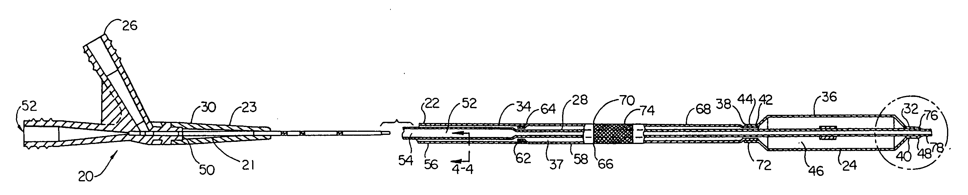
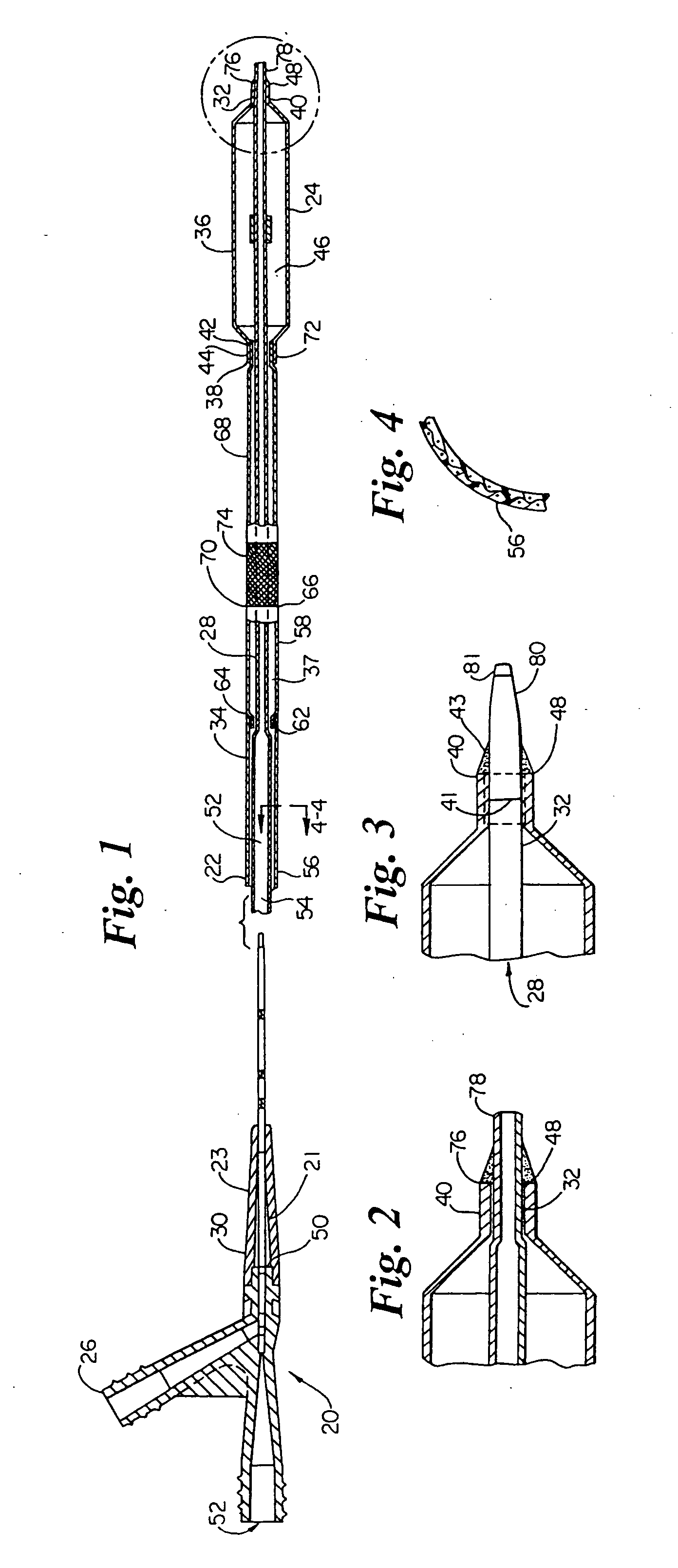
[0027] Referring now to the drawings, FIG. 1 is a cross-sectional view of an over-the-wire balloon catheter showing a preferred embodiment of the present invention. The balloon catheter 20 includes a shaft assembly 22 and a balloon assembly 24 connected proximate its distal end. A conventional OTW-type manifold assembly 26 is connected to the proximal end ...
PUM
Abstract
A tubular transition member having an annular wall with at least one cut extending through the annular wall is disclosed for controlling a transition in stiffness of a catheter from a stiffer more pushable proximal section to a more flexible and trackable distal section and increasing kink resistance. The transition member may extend across the junction formed between the stiffer proximal section and the more flexible distal section. The transition member may be used in conjunction with any type of catheter including single-operator-exchange type catheters, over-the wire type catheters, and / or fixed-wire type catheters.
Description
CROSS-REFERENCE TO RELATED APPLICATIONS [0001] This application is a continuation of co-pending U.S. application Ser. No. 10 / 285,948, filed Nov. 1, 2002; which is a continuation of U.S. application Ser. No. 09 / 534,870, filed Mar. 24, 2000, now U.S. Pat. No. 6,475,209; which is a divisional of U.S. application Ser. No. 09 / 241,995, filed Feb. 2, 1999, now U.S. Pat. No. 6,048,338; which is a continuation-in-part of U.S. application Ser. No. 08 / 950,864, filed Oct. 15, 1997, now U.S. Pat. No. 5,891,110; the disclosures of which are all incorporated herein by reference.TECHNICAL FIELD [0002] This invention relates to the field of intravascular medical devices, and more particularly, to intravascular catheters that use a relatively stiff proximal section and a more flexible distal section for improved pushability, trackability and crossability. BACKGROUND OF THE INVENTION [0003] Intravascular diseases are commonly treated by relatively non-invasive techniques such as percutaneous translumi...
Claims
Application Information
Patent Timeline
Application Date:The date an application was filed.
Publication Date:The date a patent or application was officially published.
First Publication Date:The earliest publication date of a patent with the same application number.
Issue Date:Publication date of the patent grant document.
PCT Entry Date:The Entry date of PCT National Phase.
Estimated Expiry Date:The statutory expiry date of a patent right according to the Patent Law, and it is the longest term of protection that the patent right can achieve without the termination of the patent right due to other reasons(Term extension factor has been taken into account ).
Invalid Date:Actual expiry date is based on effective date or publication date of legal transaction data of invalid patent.
Patent Type & AuthorityApplications(United States)

