

Aspiration control via flow or impedance
a flow or impedance technology, applied in the direction of suction pumps, intravenous devices, other medical devices, etc., can solve the problems of lack of occlusion detection, difficulty in operating vacuum controlled systems in flow controlled mode, and varying amounts of effort required to effectively and safely remove tissue and fluid
- Summary
- Abstract
- Description
- Claims
- Application Information
AI Technical Summary
Problems solved by technology
Method used
Image

Examples
Embodiment Construction
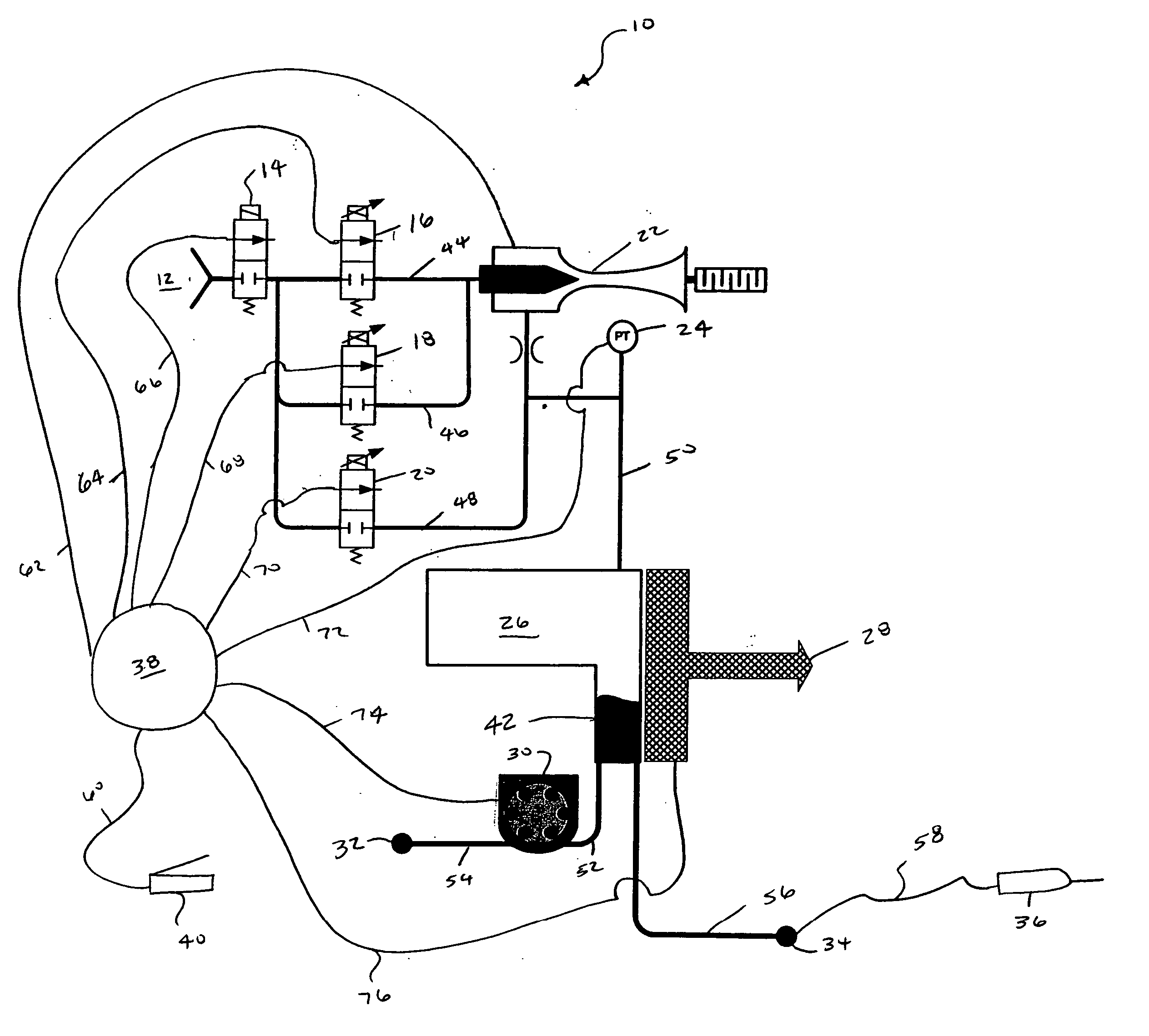
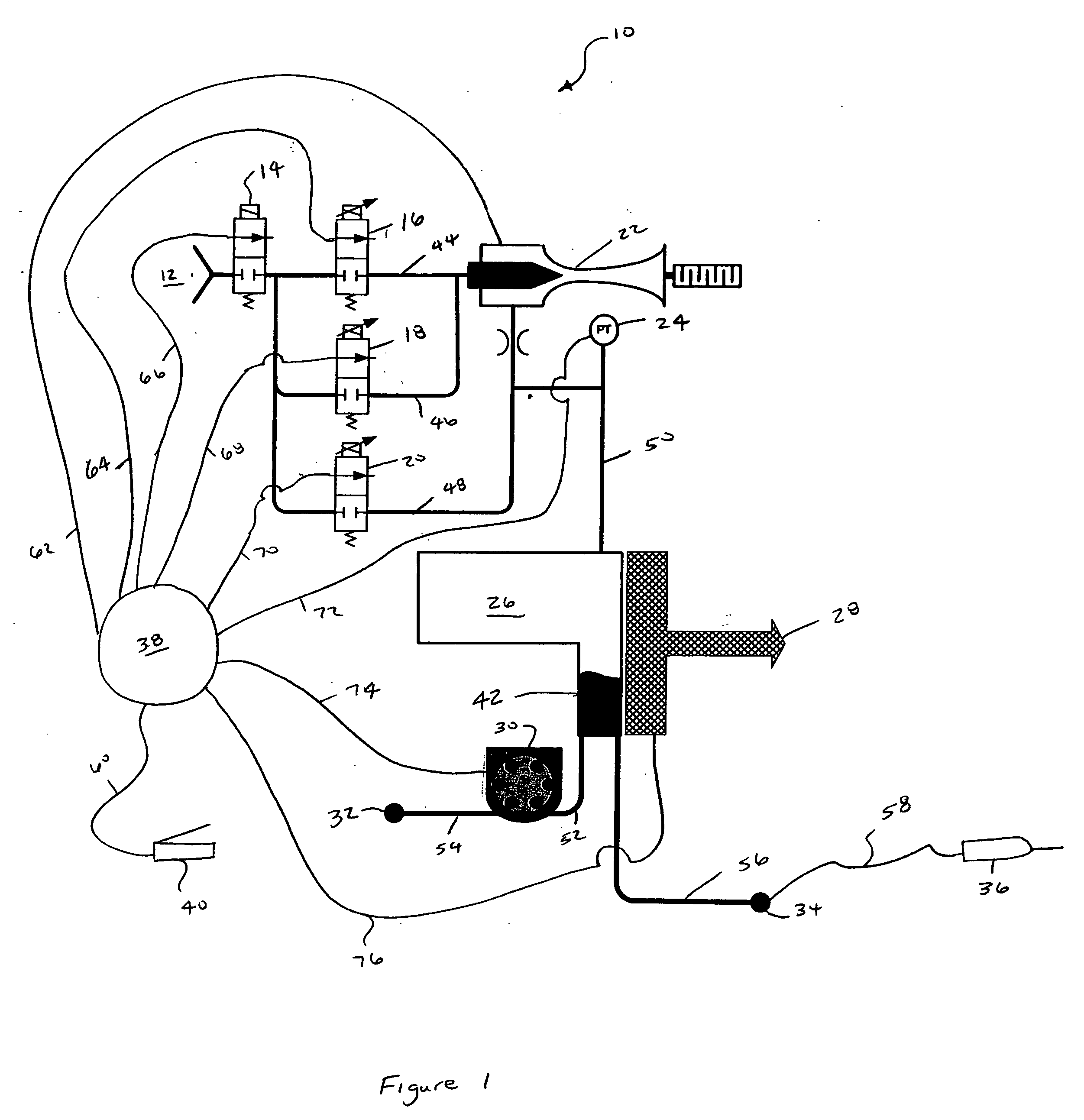
[0013] The preferred embodiment of the present invention and its advantages is best understood by referring to FIG. 1 of the drawings. Microsurgical system 10 includes a pressurized gas source 12, an isolation valve 14, a vacuum proportional valve 16, an optional second vacuum proportional valve 18, a pressure proportional valve 20, a vacuum generator 22, a pressure transducer 24, an aspiration chamber 26, a fluid level sensor 28, a pump 30, a collection bag 32, an aspiration port 34, a surgical device 36, a computer or microprocessor 38, and a proportional control device 40. The various components of system 10 are fluidly coupled via fluid lines 44, 46, 48, 50, 52, 54, 56, and 58. The various components of system 10 are electrically coupled via interfaces 60, 62, 64, 66, 68, 70, 72, 74, and 76. Valve 14 is preferably an “on / off” solenoid valve. Valves 16-20 are preferably proportional solenoid valves. Vacuum generator 22 may be any suitable device for generating vacuum but is prefe...
PUM
 Abstract
Description
Claims
Application Information