Eureka AIR delivers breakthrough ideas for toughest innovation challenges, trusted by R&D personnel around the world.

Network architecture

a network architecture and network technology, applied in the field of digital networks, can solve the problems of increasing complexity, problems such as the problem of flat address spaces and the naming of ports in networks, and achieve the effect of simplifying and improving the efficiency of information transport across networks

Active Publication Date: 2007-01-04
TRIA NETWORKS SYST
View PDF6 Cites 41 Cited by
  • Summary
  • Abstract
  • Description
  • Claims
  • Application Information

AI Technical Summary

Benefits of technology

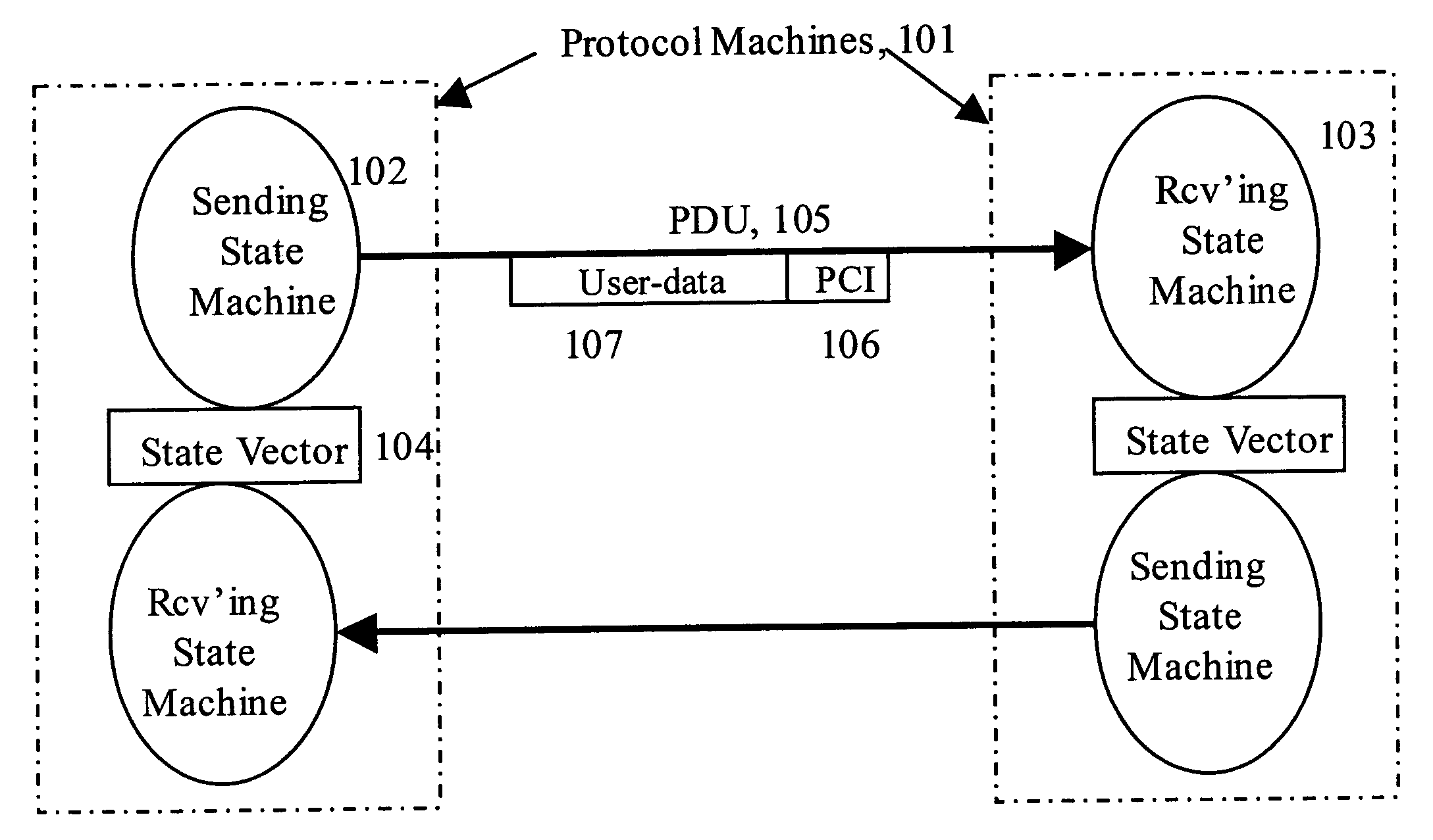
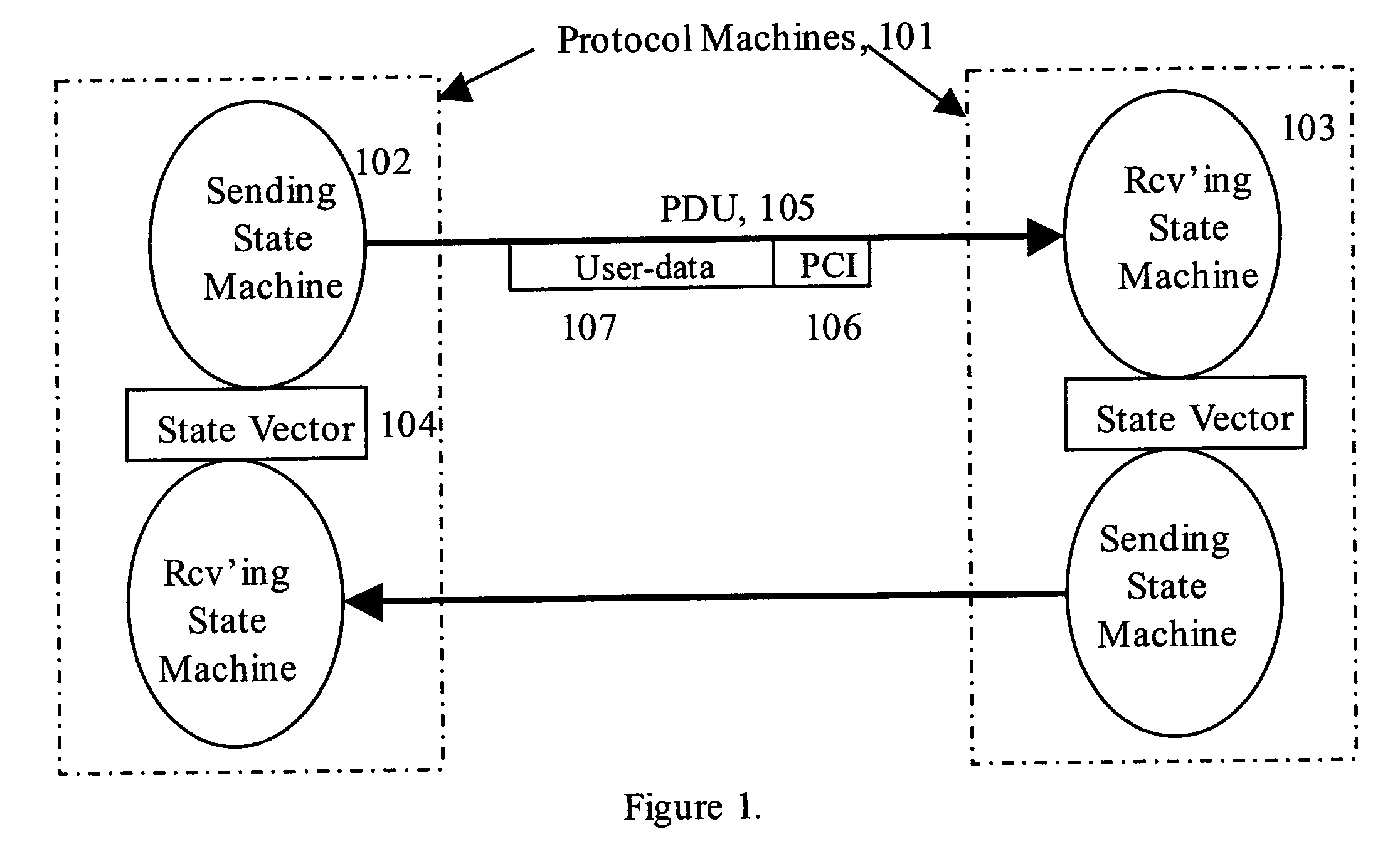
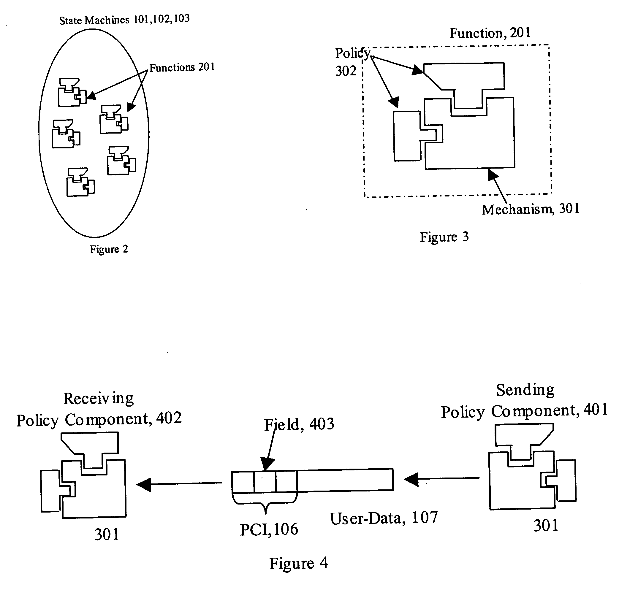
[0010] Disclosed are methods and systems for simpler and more efficient transport of information across networks. The methods described below are intended to work alongside or replace conventional Internet protocols to address and obviate current scaling limits of the Internet and other networks.
[0012] In another aspect of the invention, topological addressing methods and systems are provided to enable improved transport. In a further aspect, by utilizing the invariant structure of protocols, combined with topological addressing to identify the location of elements of a network, a repeating, recursive structure is obtained that enables scaling and other significant improvements over conventional network methods.

Problems solved by technology

The first represents a fairly constrained problem that considers addressing, error detection and recovery, flow control, sequencing, etc.
The result has been growing complexity.
In addition, the use of addressing in data networks has been a major problem almost from the beginning of computer networks.
As networks grew, flat address spaces and the naming of ports became problematic for networks.
But as it became millions and billions the problem became more severe.
But once computers needed more than one connection for redundancy, problems arose.
Since each connection had a separate address, the routing algorithms in the network could not tell that two addresses actually went to the same place.
But this only accounts for issues of route aggregation and does not address issue of multihoming and mobility.
However, there have always been problems with this approach both in terms of accommodating requirements of applications and its ability to scale.

Method used


Image

  • Network architecture
  • Network architecture
  • Network architecture

Examples


first embodiment

[0118] The embodiment shown in FIG. 7 allocates the mechanisms between the error control and relaying protocols in a form that closely parallels the placement of functions found in protocols like TCP and IP, or TP4 and CLNP, or XNS. The common PCI, 703, provides the PCI elements common to all PDUs. Relaying and multiplexing, 702, is performed followed by the error and flow control, 701, on a per flow basis.

second embodiment

[0119] The embodiment shown in FIG. 8, however, allocates tightly-bound mechanisms to the relaying and multiplexing protocol, 802, and loosely bound mechanisms to the error and flow control protocol, 801. This also implies that the relaying and multiplexing protocol only requires a 2-way handshake any state synchronization while the error and flow control protocol requires a 3-way handshake. The common PCI, 803, provides the PCI elements common to all PDUs. In this embodiment, the relaying and multiplexing protocol is the primary vehicle for data transfer with the error and flow control protocol being out-of-band. An Application protocol is a specialization of the relaying and multiplexing protocol with additional functions in the data transfer phase. The error and flow control protocol would only be present for application protocols only if one or two phase commits was required.

[0120] These embodiments apply only to the implementation and are fully and completely equivalent in the...


PUM


Abstract

Disclosed are methods and systems for improved information transfer across networks, including network protocols with invariant structure, topological addressing, and recursive network structures.

Description

CROSS-REFERENCE TO RELATED APPLICATIONS [0001] The present application for patent claims the priority of commonly owned provisional application for United States Patent No. 60 / 452,812 filed Mar. 7, 2003, incorporated herein by reference.FIELD OF THE INVENTION [0002] The present invention relates generally to digital networks, and in particular, to a parameterized, recursive network architecture with topological addressing. BACKGROUND OF THE INVENTION [0003] Conventional computer networks typically require protocols to maintain shared state between the communicating entities. These generally take one of two forms: those concerned exclusively with the transfer of data; and those concerned with applications. The first represents a fairly constrained problem that considers addressing, error detection and recovery, flow control, sequencing, etc. Application protocols serve the entire range of applications and hence take on many forms. But even here, within specific problem areas, there c...

Claims


Application Information

Patent Timeline
Patent Type & Authority Applications(United States)
IPC IPC(8): G06F15/16G06FG06F13/10G06F15/173G06F15/177H04L12/56H04L47/21H04L47/2416
CPCH04L41/145H04L61/10H04L47/10H04L47/12H04L47/193H04L47/21H04L47/2416H04L49/90H04L61/2061H04L69/08H04L69/06H04L69/24H04L69/32H04L69/329H04L69/325H04L67/42H04L67/306H04L67/2823H04L65/605H04W80/04H04L61/2084H04W40/248H04W8/26H04W8/087H04Q3/0095H04Q3/0054H04L65/1069H04L45/00H04L41/5025H04L41/00G06F21/10H04L61/5084H04L61/5061H04L65/765H04L67/01H04L67/565H04L41/0896H04L41/147
Inventor DAY, JOHN
Owner TRIA NETWORKS SYST
Why Eureka
Eureka Blog
Learn More