
Solver for a restrained deformable system with released degrees of freedom

Active Publication Date: 2007-01-11
DASSAULT SYSTEMES
View PDF15 Cites 4 Cited by
  • Summary
  • Abstract
  • Description
  • Claims
  • Application Information

AI Technical Summary

Benefits of technology

[0014] The standard “constraints factorization” procedure consists in generating a set of coupled constraint equations, written in terms of global displacement components, then transforming it into an equivalent form, from which all dependent degrees of freedom are eliminated, then substituting this form in the global system of equilibrium equations (assumed to be constructed from elementary stiffness matrices and load vectors rotated in the global reference frame prior to assembly), and finally projecting this system on the nullspace of the set of coupled constraint equations, thereby eliminating all dependent degrees of freedom and unknown Lagrange multipliers and transforming the global system of equilibrium equations into a more compact and invertible system of equations.
[0017] Once the appropriate system of equilibrium equations has been assembled, the uncoupled constraint equations are taken into account by simple row and column elimination operations, upon direct inspection of the assembled stiffness matrix and load vector. The resulting system of equations is termed “hybrid” since its unknowns are not displacement components relative to a unique reference frame. Nevertheless, all dependent degrees of freedom and unknown Lagrange multipliers have been eliminated and the transformed system of equilibrium equations is again compact and invertible.
[0021] Specifically, the invention provides in a first embodiment a process for determining the behaviour of a system submitted to predetermined load and displacement boundary conditions, using finite element analysis, the predetermined displacement boundary conditions including at least one degree of freedom release at one node of the system wherein the process comprises a plurality of incremental steps, wherein each incremental step comprises computing for a finite element of the system a displacement vector, at the nodes of the finite element, by minimizing an energy of the system when submitted to a fraction of the predetermined displacement; wherein the step of minimizing is carried out, for a node having a released degree of freedom, in a local frame of reference, and wherein a released degree of freedom at said node is expressed along one axis of the local frame of reference.
[0030] the process further comprises, during a step of computing, computing at a node of finite element a rotation transforming an elementary frame of reference into the nodal frame of reference, minimized energy depending on the computed rotation;
[0032] the step of minimizing the energy is carried out iteratively and comprises computing a scalar product of a residual and of a displacement variation and stopping the iterations according to a value of the scalar product.

Problems solved by technology

The prior art solution of factorising the constraints may involve long and complex computation, especially when the released degrees of freedom do not correspond to the axes of the global reference frame.

Method used


Image

  • Solver for a restrained deformable system with released degrees of freedom
  • Solver for a restrained deformable system with released degrees of freedom
  • Solver for a restrained deformable system with released degrees of freedom

Examples


Embodiment Construction

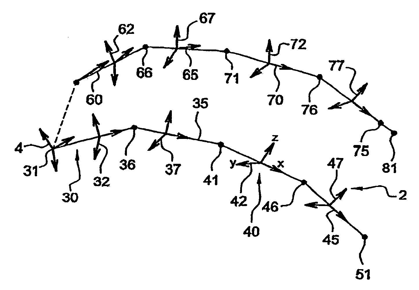
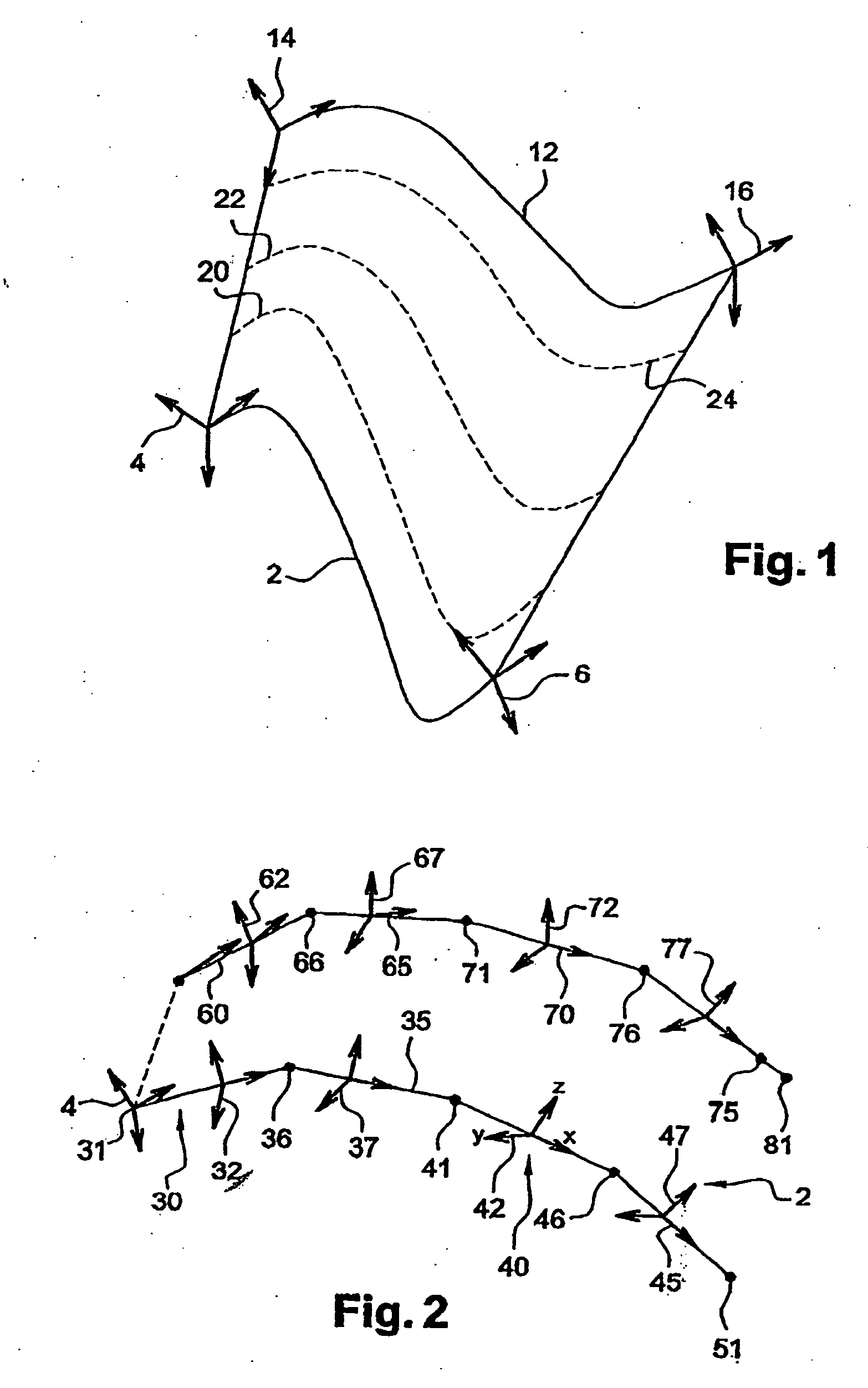
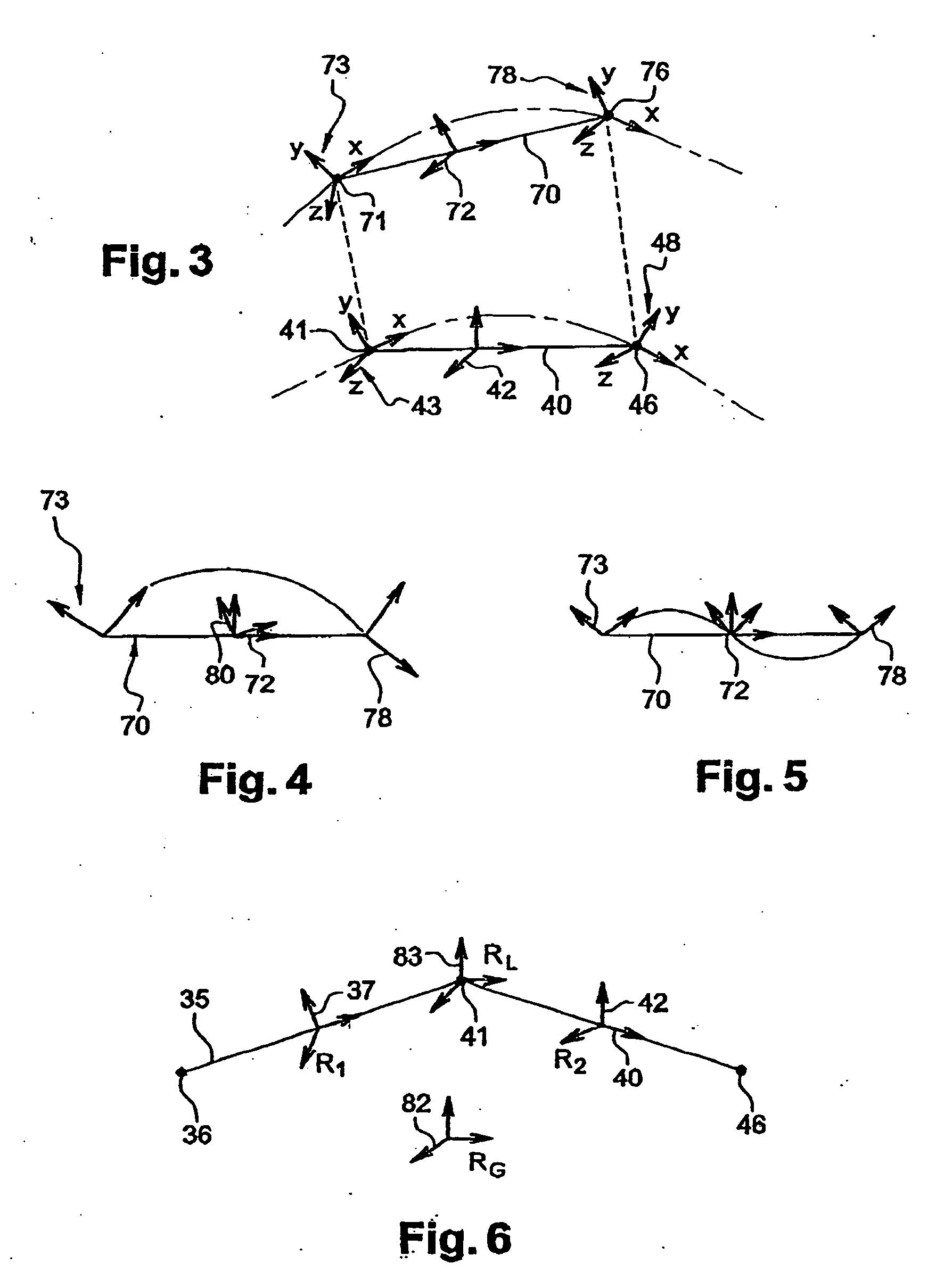
[0041] The description of slender-body flexible systems in reference to FIGS. 1-5 is useful for understanding the general operation of a solver, even though it does not address specifically the problem of limited degrees of freedom, but rather co-rotational updating in the prior art incremental total Lagrangian formulation. For the sake of clarity, the process disclosed in the NAFEMS World Congress paper (thereafter the NAFEMS paper) is discussed again here. In the first part of the present description, one considers the case where the predetermined reference displacement of the flexible system at both ends is fully determined.

[0042] The purpose of the process is to determine the behaviour of the flexible system, when submitted to predetermined displacement boundary conditions. Reference 2 in FIG. 1 designates the starting configuration of the flexible system. At both ends of the system, frames of reference 4 and 6 are represented. These frames of reference are local frames of refe...


PUM


Abstract

A process of using finite element analysis for determining the behaviour of a system, submitted to predetermined load and displacement boundary conditions with a degree of freedom relative to a local coordinate system released at one node of the system. For a geometrically non-linear solution scheme, a plurality of incremental steps are carried, for which computing for a finite element of the system a displacement vector at the nodes of the finite element is performed by minimizing the energy of the system. For a geometrically linear solution scheme, a single solving step is carried, for which similar steps of computing for a finite element and timely minimizing of the system's energy are performed. The step of minimizing is carried out, for a node having a released degree of freedom, in a local frame of reference, and the released degree of freedom at the node is expressed along one axis of such frame. Such hybrid reference frames allow expressing and taking into account in the global formulation the constraints of the non-released degrees of freedoms in a simple manner, without having to factorise constraints.

Description

CROSS REFERENCE TO RELATED APPLICATIONS [0001] This application claims priority to European Patent Application No. 06290450.3, filed on Mar. 21, 2006, which claims priority to European Patent Application No. 05290790.4, filed on Apr. 8, 2005. FIELD OF THE INVENTION [0002] The invention relates to the field of computer programs and systems, more specifically to part design programs and such constraints-based systems. BACKGROUND OF THE INVENTION [0003] A number of systems and programs are offered on the market for the design of parts or assemblies of parts, such as the one provided by the applicant under the trademark CATIA. These so-called computer-aided design (CAD) systems allow a user to construct and manipulate complex three-dimensional (3D) models of parts or assemblies of parts. These systems and programs use various constraints for defining models. The set of constraints is solved by the system when the model is edited. The program or system used for solving the set of constra...

Claims


Application Information

Patent Timeline
IPC IPC(8): F41G7/00
CPCG06F17/5018G06F2217/06G06F2217/36Y10S706/902Y10S715/964Y10S706/92Y10S706/919Y10S715/961G06F2111/04G06F2113/16G06F30/23A61F5/37A61F5/0013A61H19/40A61H2205/087
Inventor DE HILLERIN, CHARLES-ANDREVOEGELE, SEBASTIEN
Owner DASSAULT SYSTEMES
Learn More