
High-density hollow weave ground fabric

a high-density, weave fabric technology, applied in weaving, pedestrian/occupant safety arrangements, vehicular safety arrangements, etc., can solve the problems of reducing the mechanical strength of the fabric, affecting the quality of the ground fabric, and affecting the containment ability, etc., to achieve excellent fabric quality, reduce the effect of air leakage, and be easily deployed

Active Publication Date: 2007-01-11
ASAHI KASEI KK
View PDF6 Cites 33 Cited by
  • Summary
  • Abstract
  • Description
  • Claims
  • Application Information

AI Technical Summary

Benefits of technology

[0014] An object of the present invention is to solve the above-mentioned problems in the prior art by providing a high-density hollow weave fabric suitable for a curtain-shaped air bag which is rapidly inflatable or deployable with extremely little air leakage, is free from fluffs of warp yarn because the tension applied to the warp yarn during the weaving operation is small, hardly generates wrinkles in a boundary between a double-layer hollow weave portion and a single-layer weave portion during coating, is excellent in fabric quality and high in air-holding ratio after inflation and deployment. 2. Means for Solving the Problem

Problems solved by technology

In the prior art, a boundary between the double layer portion and the single layer portion has often been problematic due to its weave structure in that fluffs appear on the high-density hollow weave fabric or the mechanical strength of the fabric is lowered by the generation of wrinkles.
This, however, results in a problem in that the containment ability becomes worse.
Also, as the configuration of the air bag is complicated, the sewing operation is troublesome.
While it is necessary to use a single-layer weave portion larger in width to maintain the inflated state of the hollow weave portion, and there is a problem in that wrinkles or fluffs generate in a boundary between the hollow weave portion and the single-layer weave portion since a crimpability of a yarn in the single-layer weave portion is larger than that of a yarn in the hollow weave portion and also a cover factor of the fabric is larger, it is impossible to suppress air leakage for several seconds after inflation and deployment.
Particularly, there is a problem in that wrinkles are liable to be generated due to heat or tension applied to the fabric when the surface of the fabric is coated with silicone resin or urethane resin to be suitable for the air bag.
However, there is a problem in that, while the strength of the seamed portion itself is improved, it is still impossible to prevent air from leaking through the boundary between the double-layer hollow weave portion and the single-layer weave portion.
However, there is no concrete description of a weave pattern of the single-layer weave portion therein and, as the width of the single-layer weave portion is too large, if such a fabric is used as a curtain-shaped air bag, there is a problem that warp yarns may be fluffy and the fabric may be wrinkled during coating.
However, this is problematic because the weave pattern in the single-layer portion is solely a 2 / 2 basket weave (throughout the specification, the term basket weave is used as the representing therm for basket weave including small-repeat basket weave such as hopsack weave, mat weave monk's weave and the like.) and the influence of a fineness of a yarn on the resulted fabric is not at all taken into account.
As the 2 / 2 basket weave pattern has a tight structure and a load applied to a yarn is large, if a plurality of such weave patterns are adjacently arranged, there is a problem in that wrinkles are generated in a boundary between the double-layer hollow weave portion and the singe-layer weave portion to increase a bulkiness of the fabric, which deteriorates the containment ability.
Also, the air leakage becomes high due to the irregularity of coating caused by the wrinkles.
Accordingly, the air leakage is still unsatisfactory.
However, in the high-density hollow weave fabric, if any such tight weave pattern like 2 / 2 basket weave is placed further outside thereof, wrinkles are generated in a bag portion interposed between the 2 / 2 basket weave portions or in the exterior of the 2 / 2 basket weave portion to cause irregular coating, resulting in air leakage.

Method used

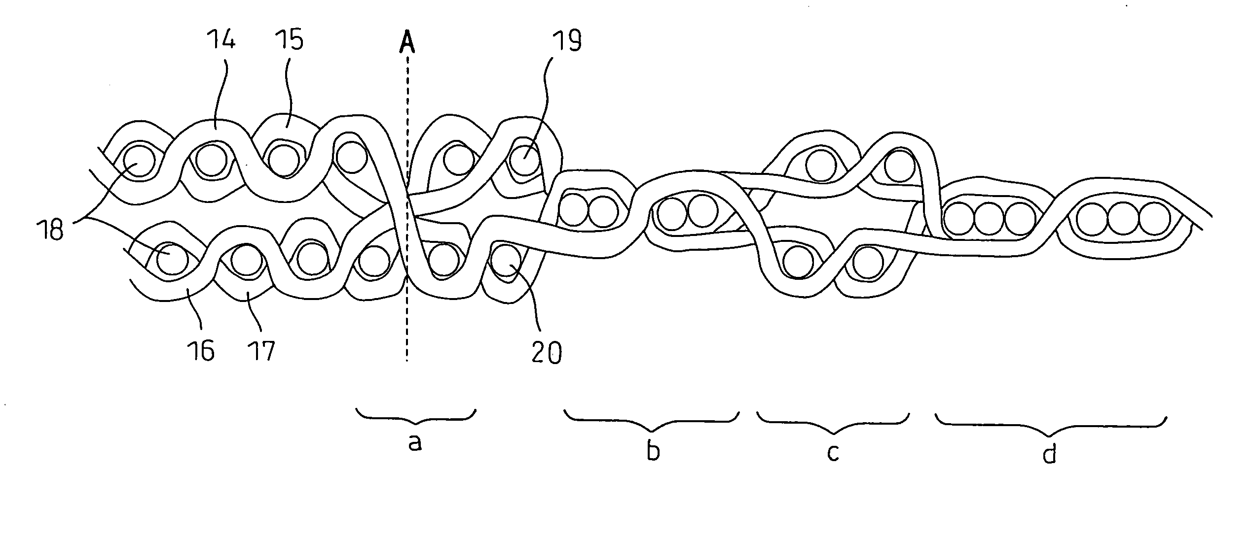
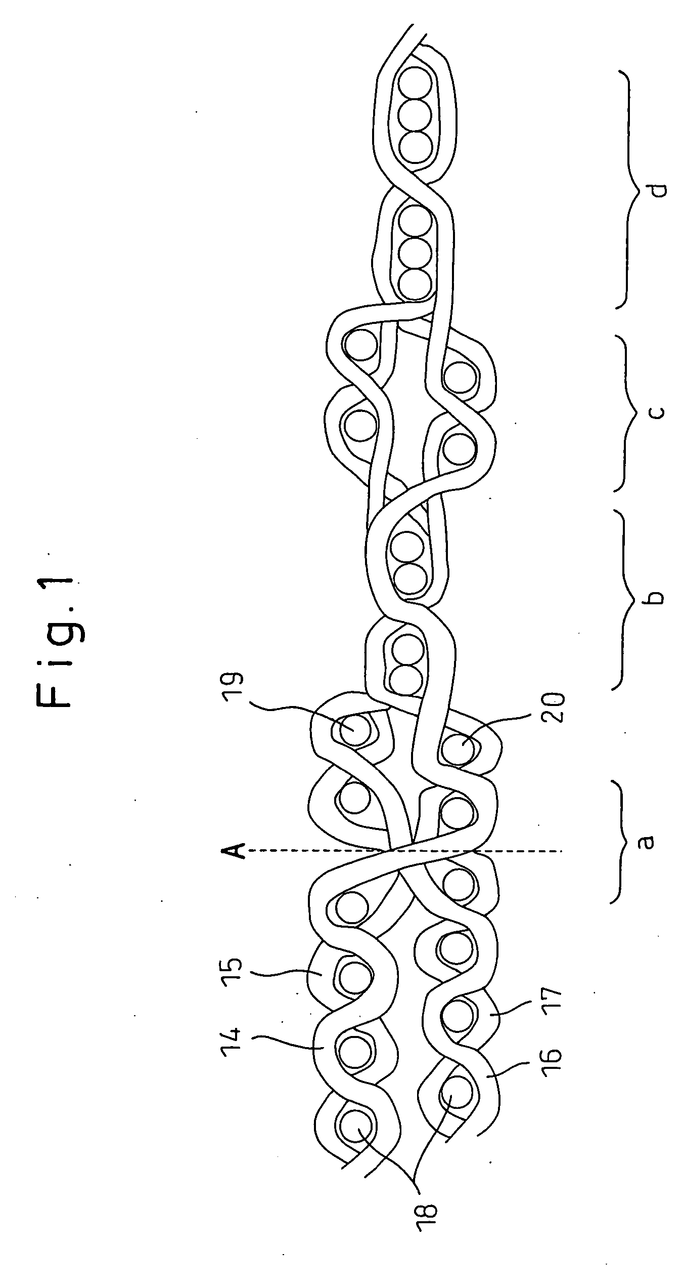
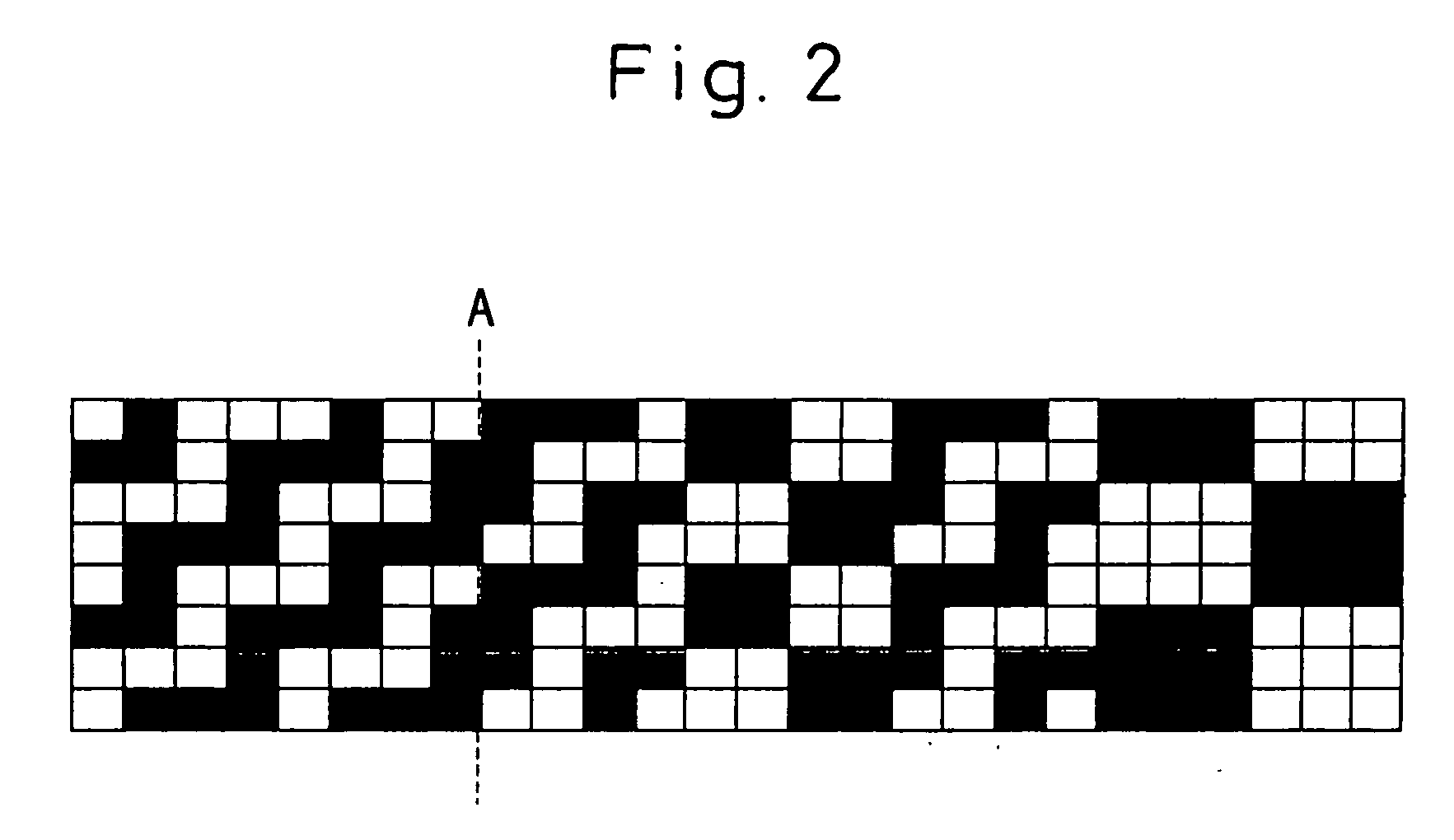

Image

  • High-density hollow weave ground fabric
  • High-density hollow weave ground fabric
  • High-density hollow weave ground fabric

Examples


example 1

[0134] A gray fabric was woven from non-twisted polyhexamethylene adipamide filament yarns having the yarn size of 235 dtex and the fiber fineness of 3.3 dtex, the interlaced points of 32 / m, the interlacement strength of 27% and the oil adhesion amount of 1.0% by weight used as warp yarns and weft yarns by using the above-mentioned rapier loom and electronic jacquard machine under the condition wherein a warp density on loom is 126.6 end / 2.54 cm, a weft density on loom is 136 end / 2.54 cm, a space ratio of the reed is 66.8% and a warp tension during the weaving operation is 0.25 cN / dtex. The seam zone was composed of the 2 / 2 basket weave pattern formed of six yarns, the narrow width hollow weave portion formed of four yarns and the 3 / 3 basket weave pattern formed of six yarns as seen from the double-layer hollow weave portion side. Then, this gray fabric was subjected to a scouring and setting process, and thereafter subjected to a coating process wherein an amount of 50 g / m2 of sili...

example 2

[0141] Under the same condition as in Example 1, a finished fabric having the warp density of 137 end / 2.54 cm and the weft density of 146 end / 2.54 cm was obtained, except that the warp density on loom was changed to 120.0 end / 2.54 cm. The cover factor in the narrow width hollow weave portion was 2169 on one surface.

[0142] Properties of the resultant fabric were shown on Table 1. That is, there was no loom stoppage during the weaving operation which shows that the weavability is favorable. The finished fabric was free from wrinkles and coating irregularity. The roughness of the seam zone was low and allowable, and the retention ratio of the internal pressure was also good. The fabric was soft and the adhesiveness against anti-wet heat treatment was excellent. Also, the fabric was deployable at a high speed because the yarn size is as small as 235 dtex.

example 3

[0143] Under the same condition as in Example 1, a finished fabric having the warp density of 160 end / 2.54 cm and the weft density of 142 end / 2.54 cm was obtained, except that the warp density on loom was changed to 147.4 end / 2.54 cm. The cover factor in the narrow width hollow weave portion was 2315 on one surface.

[0144] Properties of the resultant fabric were shown on Table 1. That is, the loom stoppage was extremely few which shows that the weavability is favorable. The finished fabric was free from generation of wrinkles and coating irregularity. The flatness of the boundary was favorable, and the retention ratio of the internal pressure was very good which means that the impact on the human body is small. The adhesiveness against anti-wet heat treatment was excellent. Also, the fabric was deployable at a high speed because the yarn size is as small as 235 dtex.


PUM

PropertyMeasurementUnit
Fractionaaaaaaaaaa
Sizeaaaaaaaaaa
Densityaaaaaaaaaa

Abstract

A high-density hollow weave fabric for an air bag is provided, wherein an inflatable double-layer hollow weave portion is encircled on the outer periphery thereof with a seam zone including a reversible figured weave pattern and a basket weave pattern. In the seam zone, the reversible figured weave pattern is closest to the boundary of the inflatable double-layer hollow weave portion, and a first weave portion including the basket weave pattern, a narrow width hollow weave portion and a second basket weave patterns continue in this order. The inventive fabric is woven without the generation of fluffs and wrinkles, and the wrinkle-free coating is provided in the boundary between the double-layer hollow weave portion and the seam zone encircling the former. By using this high-density hollow weave fabric, it is possible to make the curtain-shaped air bag deployable at a high speed while preventing gas from leaking.

Description

TECHNICAL FIELD [0001] The present invention relates to a high-density hollow weave fabric suitably used for an air bag that is one of the safety devices in a vehicle such as an automobile. Particularly, the invention relates to a high-density hollow weave fabric for a side curtain air bag, having a complicated configuration, for the side protection of a passenger when a vehicle is impacted in the lateral direction. BACKGROUND ART [0002] Recently, it has been required that the safety of a passenger, upon a collision, is improved. The mounting rate of various air bags has, thus, increased. An air bag is an inflatable cushion which is rapidly deployed and inflated, with gas flowing from an inflator into the inflatable cushion, when a sensor detects an impact upon a head-on collision or lateral collision of a vehicle, so that the impact applied to the passenger is mitigated to protect a human body due to the cushioning action of the inflated bag. [0003] The air bag was initially applie...

Claims


Application Information

Patent Timeline
IPC IPC(8): B60R21/235D03D13/00B60R21/16B60R21/232D03D1/02D03D11/00D06M15/643
CPCB60R21/232B60R21/235D03D1/02B60R2021/23547B60R2021/23514Y10T442/3179B60R21/16
Inventor OKUNO, TOKIOKOJIMA, MIYOKO
Owner ASAHI KASEI KK
Learn More