Oscillator circuit and method for adjusting oscillation frequency of same

a technology of oscillator and oscillator frequency, which is applied in the direction of oscillator generator, pulse automatic control, pulse technique, etc., can solve the problems of increasing the power consumption, test time, and cost of the oscillator, and the system may not function correctly, etc., to achieve stable operation

Active Publication Date: 2007-01-11
SAMSUNG ELECTRONICS CO LTD
View PDF7 Cites 16 Cited by
  • Summary
  • Abstract
  • Description
  • Claims
  • Application Information

AI Technical Summary

Benefits of technology

[0017] Accordingly, various embodiments of the present invention are provided to address the need for power,

Problems solved by technology

Accordingly, if the output frequency of the oscillator does not correspond to a target frequency of the system, the system may not function correctly.
Un

Method used


Image

  • Oscillator circuit and method for adjusting oscillation frequency of same
  • Oscillator circuit and method for adjusting oscillation frequency of same
  • Oscillator circuit and method for adjusting oscillation frequency of same

Examples


Embodiment Construction

[0030] Exemplary embodiments of the invention are described below with reference to the corresponding drawings. These embodiments are presented as teaching examples. The actual scope of the invention is defined by the claims that follow.

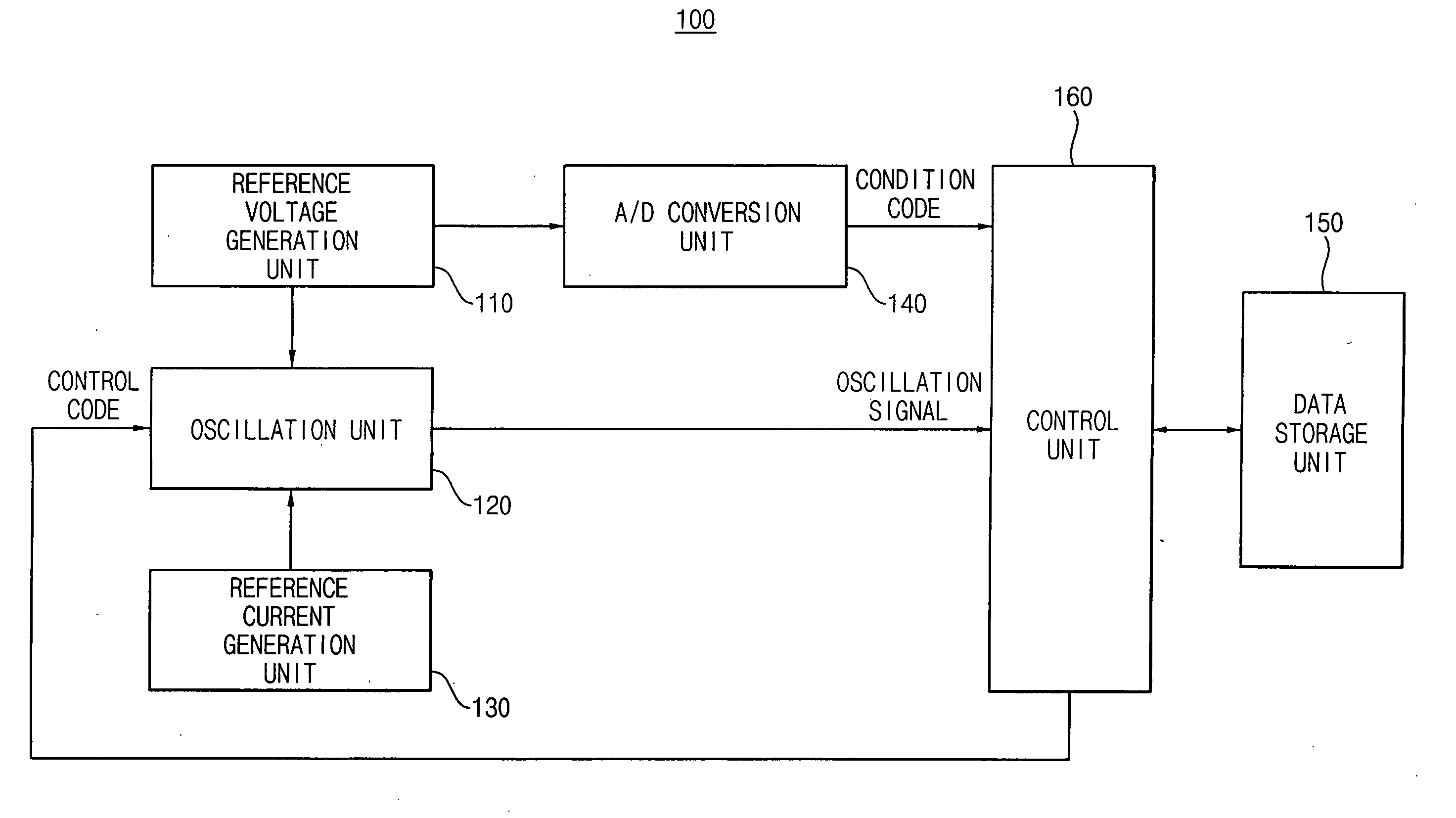
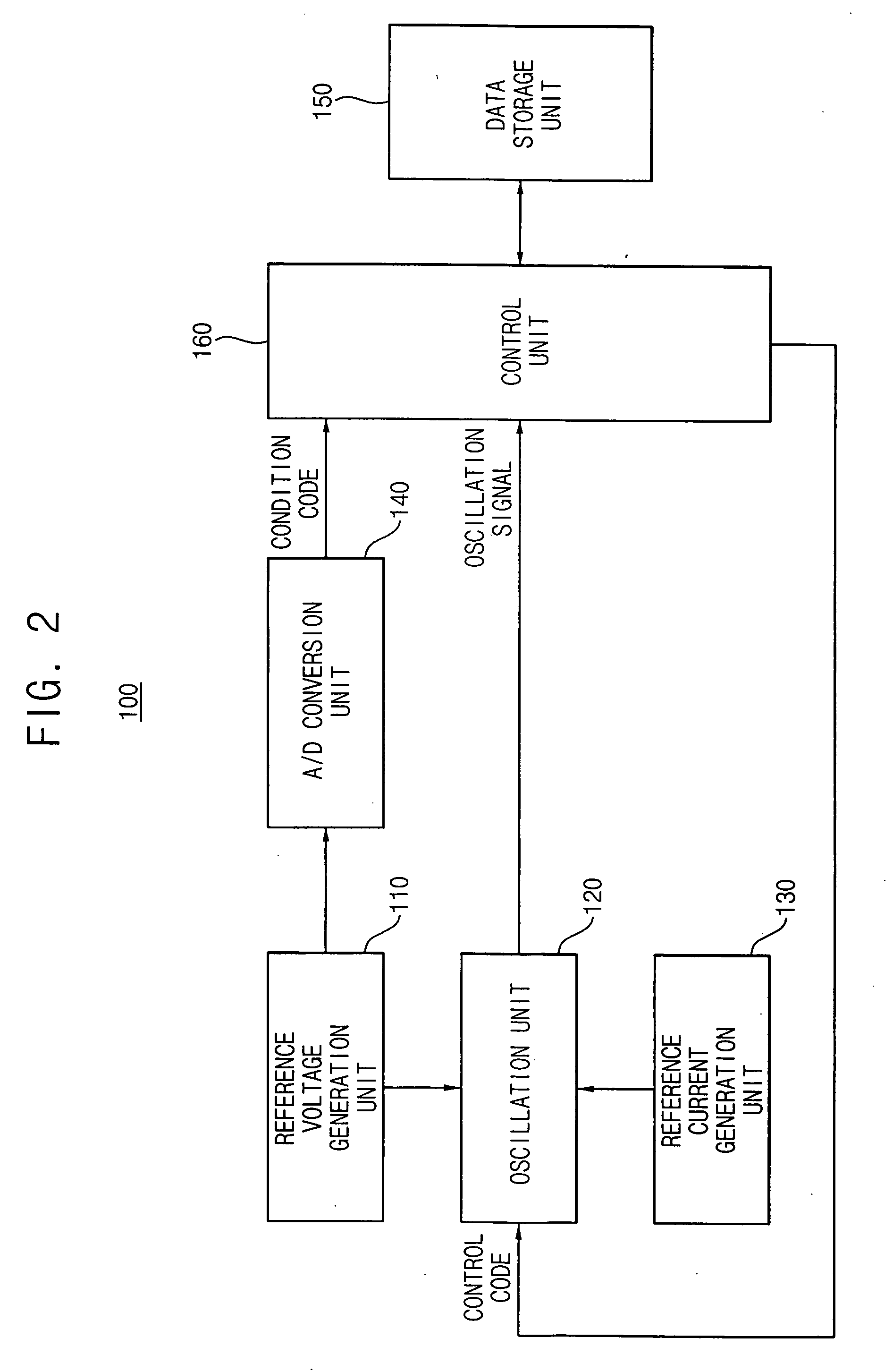
[0031]FIG. 2 is a block diagram of an oscillator 100 according to an exemplary embodiment of the invention.

[0032] Referring to FIG. 2, oscillator 100 includes a reference voltage generation unit 110, an analog-to-digital (A / D) conversion unit 140, a reference current generation unit 130, an oscillation unit 120, and a control unit 160.

[0033] Reference voltage generation unit 110 generates a reference voltage with a level that varies continuously based on a temperature of oscillator 100 and provides the reference voltage to oscillation unit 120 and A / D conversion unit 140.

[0034]FIG. 3 is a graph illustrating output characteristics of reference voltage generation unit 110 of oscillator 100 in FIG. 2.

[0035] As illustrated in FIG. 3, the level of th...


PUM


Abstract

An oscillator comprises a data storage unit, an oscillation unit, and a control unit. The data storage unit is adapted to store a plurality of reference condition codes and a plurality of reference control codes. The oscillation unit is adapted to output an oscillation signal having an oscillation frequency that varies according to a control code. The control unit is adapted to generate the control code with a target value based on the reference condition codes and the reference control codes and a current condition code input to the control unit. Where control code has the target value, the oscillation unit outputs the oscillation signal with the oscillation frequency substantially equal to a target oscillation frequency.

Description

BACKGROUND OF THE INVENTION [0001] 1. Field of the Invention [0002] Embodiments of the present invention relate generally to oscillators and methods of adjusting the oscillation frequency of the oscillators. More particularly, embodiments of the invention relate to oscillators and methods of adjusting the oscillation frequency of the oscillators to compensate for changing external environmental factors such as temperature, and power supply voltage levels. [0003] A claim of priority is made to Korean Patent Application No. 2005-60836 filed on Jul. 6, 2005, the disclosure of which is hereby incorporated by reference in its entirety. [0004] 2. Description of Related Art [0005] An oscillator is a device used to generate a continuous output waveform. For example, an oscillator typically comprises a tuned electronic circuit adapted to generate an alternating current such as a periodic signal. Most oscillators can be roughly classified into one of two groups: external oscillators such as c...

Claims


Application Information

Patent Timeline
IPC IPC(8): H03L7/00
CPCH03K3/0231H03L1/026H03L1/00H03K2005/00071H03B5/04H03B5/08
Inventor LEE, KANG-JINKIM, JI-HYUN
Owner SAMSUNG ELECTRONICS CO LTD
Why Eureka
Try Eureka