Method and system of monitoring around a vehicle

a technology of vehicle monitoring and monitoring system, applied in the field of method and a monitoring system around a vehicle, can solve the problems that the driver cannot know which part of the vehicle will touch or run on the obstacle, and achieve the effect of facilitating the safety of the driver

Active Publication Date: 2007-01-11
HITACHI LTD
View PDF6 Cites 27 Cited by
  • Summary
  • Abstract
  • Description
  • Claims
  • Application Information

AI Technical Summary

Benefits of technology

[0006] In consideration of the above problems, an object of this invention is to provide a method and system of monitoring around a vehicle which facilitate driver's quick decisions and safety activities.
[0010] In accordance with this invention, a vehicle part which may hit an object is enhanced and displayed on screen together with the object. This facilitates driver's safety activities. In other words, the driver can quickly decide a possibility of collision of the vehicle and take an appropriate action to avoid the collision.

Problems solved by technology

Even when an obstacle is displayed together with an alarm sound, the driver cannot know what part of the vehicle will touch or run on the obstacle at a glance.

Method used


Image

  • Method and system of monitoring around a vehicle
  • Method and system of monitoring around a vehicle
  • Method and system of monitoring around a vehicle

Examples


Embodiment Construction

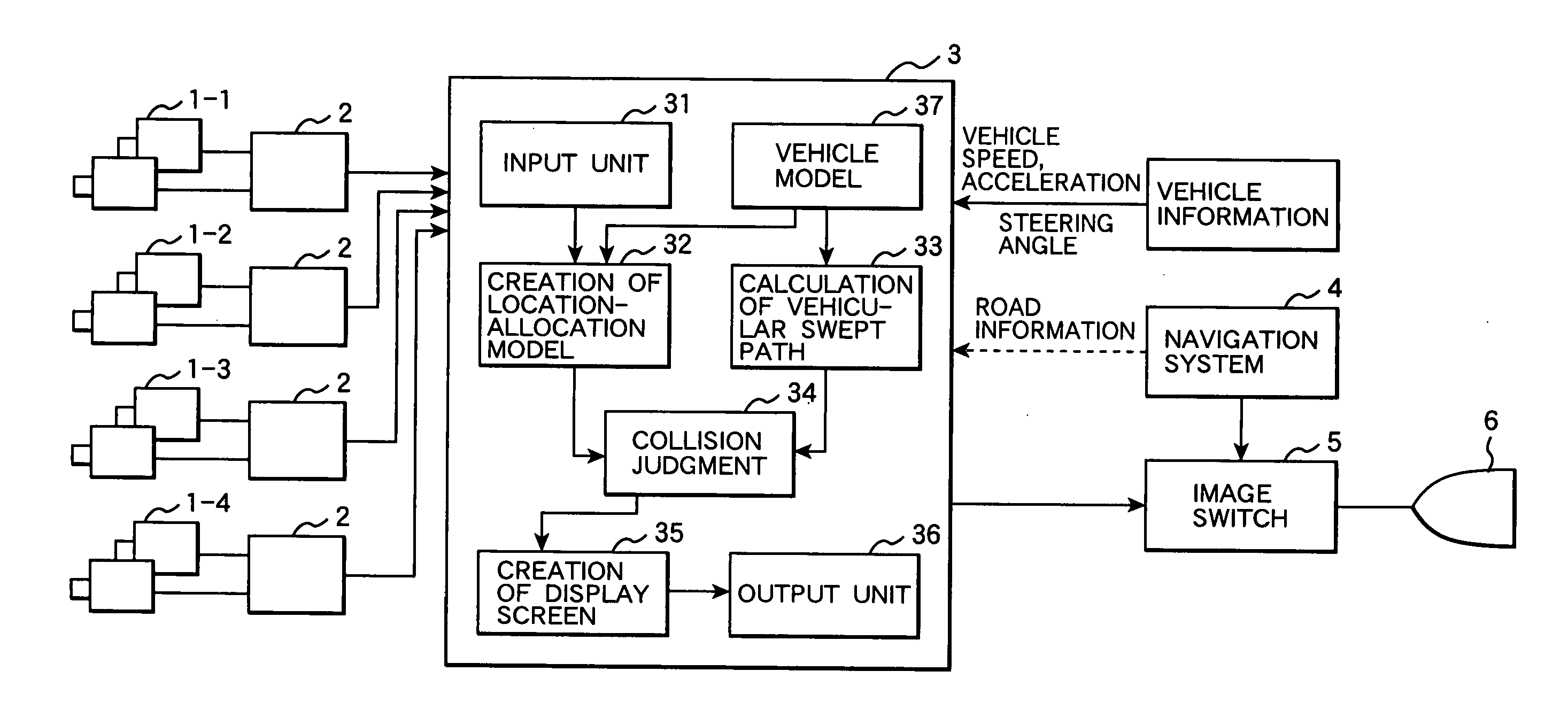
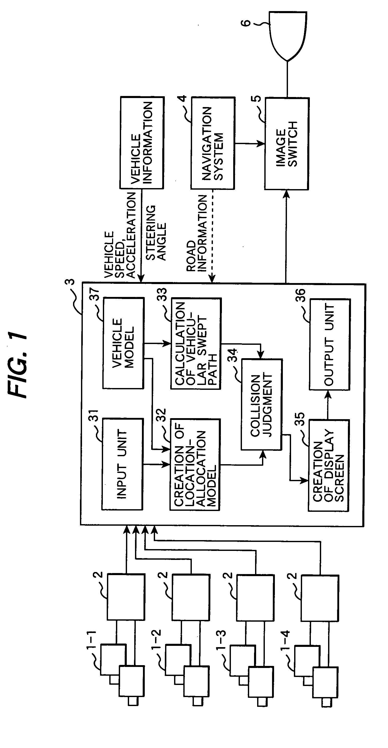
[0021] Below will be explained a preferred embodiment of this invention with reference to the accompanying drawings. FIG. 1 shows a functional block diagram of a system of monitoring around a vehicle which is an embodiment of this invention. This system is equipped with a pair of CCD cameras (1-1 to 1-4), image processor 2, integrated processing unit 3, car navigation system 4, image switching unit 5, and monitor unit 6.

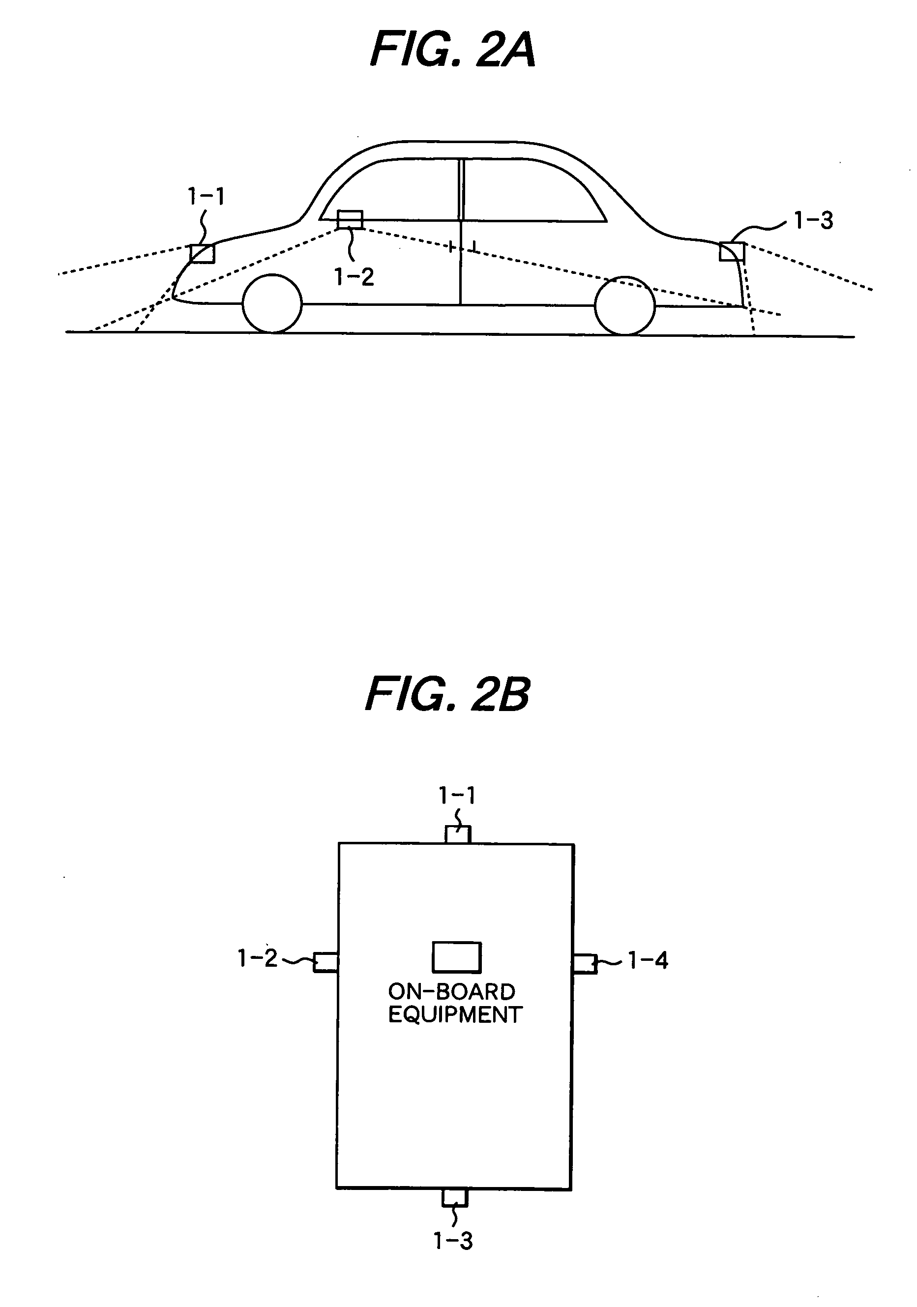
[0022] Plural CCD cameras 1 are provided on a vehicle. FIG. 2A and 2B show positions on which the cameras are provided. FIG. 2A shows a side view of the vehicle with the CCD cameras and FIG. 2B shows a top view of the vehicle. The cameras in this embodiment are respectively provided on the front end of the vehicle, near left and right side mirrors, and on the rear end of the vehicle.

[0023] A set of CCD cameras 1 and image processor 2 is called cameras with a range measurement function. Image processor 2 calculates a distance of each pixel.

[0024]FIG. 3 shows a prin...


PUM


Abstract

Integrated processing unit captures range images shot by CCD cameras which are respectively provided on front, rear, left and right sides of a vehicle and image processor. Location-allocation unit creates a location-allocation model of an obstacle from the range images and road surface images (heights of images above road surface). Vehicular swept path calculating unit calculates a swept path of each representative point. Collision decision calculates intersection of the obstacle of the location-allocation model with the swept paths of the representative points and judges whether the points cross the obstacle. When a representative point may possibly cross the obstacle, the point is enhanced and displayed together with the obstacle (object) on monitor.

Description

CLAIM OF PRIORITY [0001] The present application claims priority from Japanese application serial no. 2005-169182, filed on Jun. 9, 2005, the content of which is hereby incorporated by reference into this application. FIELD OF THE INVENTION [0002] This invention relates to a method and a system of monitoring around a vehicle using range images. BACKGROUND OF THE INVENTION [0003] In Japan, criteria of visibility to monitoring of side and front dead angles of a vehicle have been enshrined into law (in January, 2005) and provision of cameras on vehicles will be propagated rapidly. Some of already commercialized vehicles are equipped with cameras in their side mirrors and front nose and a monitor unit to display the images captured by the camera. [0004] Keiji Saneyoshi: “Obstacle detection equipment for automobile which uses stereo cameras”, First conference toward practical use of video image processing 1997. 3, Subaru Laboratory, proposes obstacle detection equipment for automobile wh...

Claims


Application Information

Patent Timeline
Patent Type & Authority Applications(United States)
IPC IPC(8): B60Q1/00
CPCB60R11/04G08G1/16B62D15/0295B62D15/029
Inventor TAKENAGA, HIROSHIASOU, YUKIO
Owner HITACHI LTD
Why Eureka
Try Eureka