Optical communication system, lighting equipment and terminal equipment used therein

a communication system and optical communication technology, applied in multiplex communication, static indicating devices, instruments, etc., can solve the problems of difficulty in maintaining color rendering properties or color temperature with this type of system and performing high-speed base band signal transmission, and achieve reliable communication, reduce the bit width of signals, and increase signal redundancy

Inactive Publication Date: 2007-01-11
BROADCOM INT PTE LTD
View PDF10 Cites 41 Cited by
  • Summary
  • Abstract
  • Description
  • Claims
  • Application Information

AI Technical Summary

Benefits of technology

[0012] The present invention provides an optical communication system that has a lighting function and is capable of high-speed signal transmission, as well as lighting equipment and terminal equipment. In particular, pseudo-noise signals are used for the spread signals; therefore, it is possible to retain white light for lighting without any great change in color temperature by high-speed modulation. That is, signal redundancy is increased and reliable communication is made possible by reducing the bit width of the signals or increasing the number of wavelengths that are differentiated.
[0013] The present invention makes multiple communications possible through the use of code domains. Even if communications by means of unrelated single wavelengths are simultaneously performed, it is possible to increase communication efficiency, regardless of the presence of interference, by optimizing the upper layer protocol. It should be noted that, when necessary, measures can be taken that include error correction and application of a time lag for modulation between broadcast data and spread codes.
[0014] The present invention does not require electrical filters or a complex system for frequency conversion and similar measures; therefore, the present invention can be inexpensively created.

Problems solved by technology

Nevertheless, by means of conventional modulation forms, it is difficult to maintain color rendering properties or color temperature with this type of system and perform high-speed base band signal transmission at the same time.

Method used


Image

  • Optical communication system, lighting equipment and terminal equipment used therein
  • Optical communication system, lighting equipment and terminal equipment used therein
  • Optical communication system, lighting equipment and terminal equipment used therein

Examples


Embodiment Construction

[0019] Preferred embodiments of the optical communication system, lighting equipment, and terminal equipment of the present invention will now be described below while referring to the attached drawings.

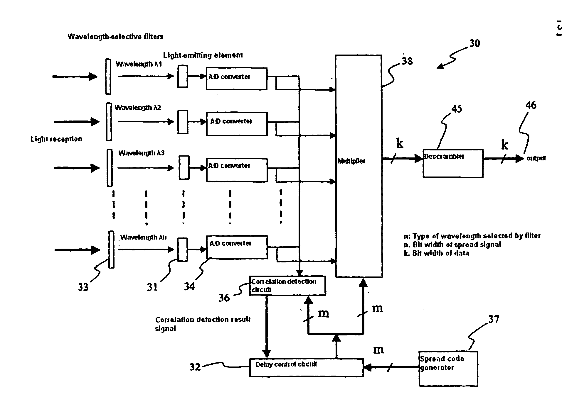
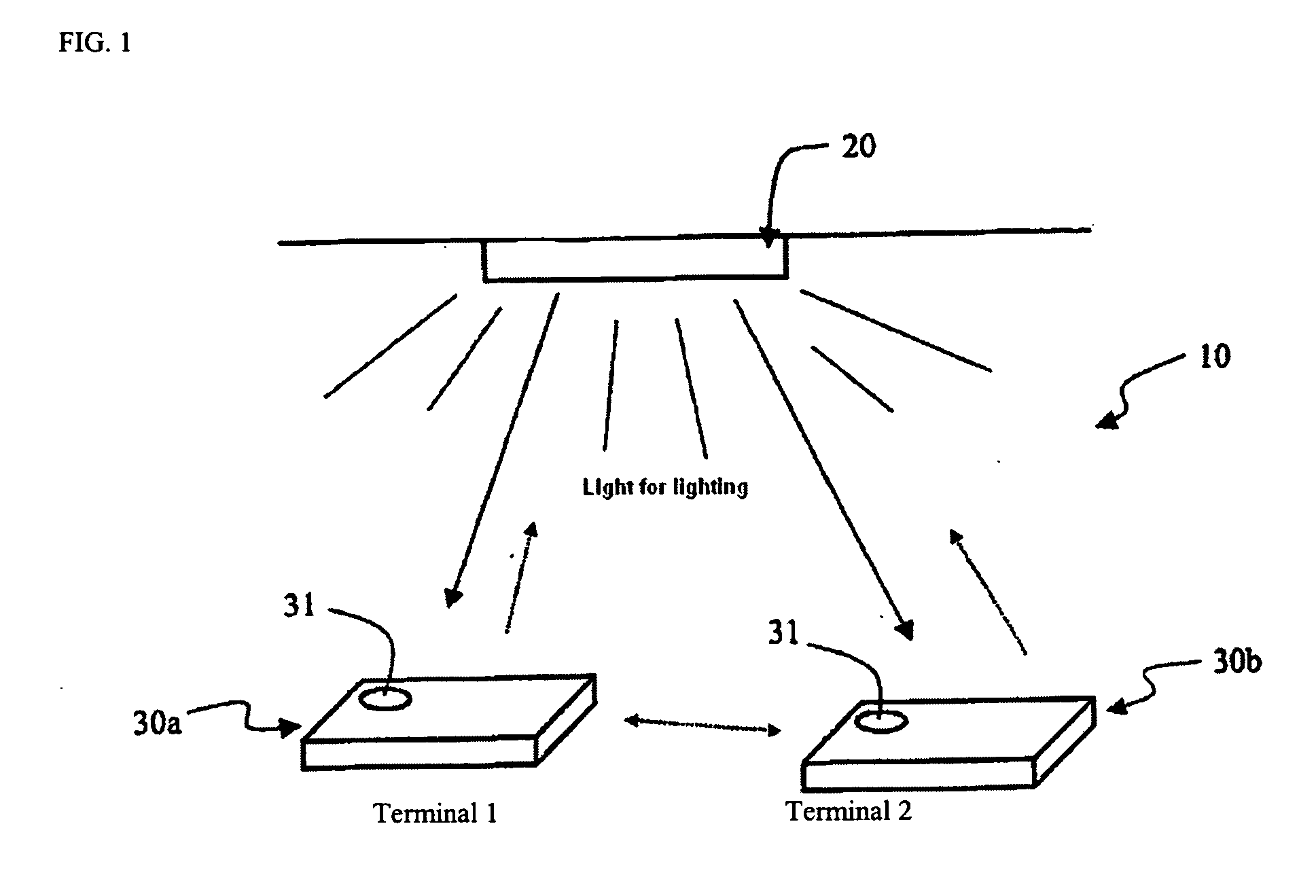
[0020]FIG. 1 is a drawing explaining the general structure of the optical communication system of the present invention. As shown in FIG. 1, a system 10 has lighting equipment 20 and terminals 30a and 30b used under a lighted environment. Terminals 30a and 30b have receiver 31 comprising light-receiving elements. As will be described below, the light for the lighting of lighting equipment 20 contains modulated signals. The terminals extract the signals using light-receiver 31. Signals are transmitted in one direction from lighting equipment 20 to terminal 30 when communication is accomplished using light for lighting as shown in FIG. 1. However, as will be mentioned later, the system can also be designed so that there are additional means capable of communication with one terminal 3...


PUM


Abstract

A communication system has lighting equipment that has transmitter comprising multiple light-emitting elements that each emit light of different wavelengths and terminal equipment that has light-receiver comprising multiple light-receiving elements that receive optical signals for each of the different wavelengths.

Description

FIELD OF THE INVENTION [0001] The present invention relates to an optical communication system that uses primarily visible light, particularly an optical communication system that uses lighting equipment as the light source. DISCUSSION OF THE BACKGROUND ART [0002] Lighting equipment that uses light-emitting diodes has been put to practical use in recent years. When light-emitting diodes are used as the light source for the purpose of lighting, a combination of light-emitting diodes that emit light of multiple different colors (usually red (R), green (G), and blue (B)) is generally used because it is easy to control color tone, color reproducibility is excellent, etc. White lighting with good color rendering properties is obtained by mixing light of these different wavelengths. [0003] On the other hand, optical communication using this type of lighting equipment has been attempted (refer to JP Unexamined Patent Application (Kokai) 2004-147,063). By means of this system, the lighting ...

Claims


Application Information

Patent Timeline
Patent Type & Authority Applications(United States)
IPC IPC(8): G09G3/32H04B10/11H04B10/116H04J14/00H04J14/02H04J14/04H04J14/06H05B37/02
CPCH04B10/116H04B10/1149H04J14/005H04J14/02
Inventor YAMAMOTO, KENJI
Owner BROADCOM INT PTE LTD
Why Eureka
Try Eureka