Plate-link chain, particularly for a motor vehicle drive system

a technology of plate link chain and drive system, which is applied in the direction of driving chain, chain elements, v-belts, etc., can solve the problems of link plate failure, link plate crack growth, and possible early failure of plate link chain, so as to reduce tension, increase the pitch radius, and increase wear.

Inactive Publication Date: 2007-01-11
SCHAEFFLER TECH AG & CO KG
View PDF8 Cites 17 Cited by
  • Summary
  • Abstract
  • Description
  • Claims
  • Application Information

AI Technical Summary

Benefits of technology

[0019] If the pitch point migrates in such a way with a known plate link chain, this leads to rotation of the rocker members in the link plates, and hence has a wear-increasing effect. In contrast, with the plate link chain according to the invention this does not lead to an increase in wear, since the forces that prevail at the upper and lower contact surfaces between the rocker members and link plates operate against rotation due to the two-point contact, and thus a migration of the pitch point is possible and is permissible in the plate link chain according to the invention.
[0020] Since the pitch point ...

Problems solved by technology

If a deflection of the plate link chain from its stretched position occurs, when the chain changes from its stretched position to a deflected position—for example when the plate link chain runs over sprocket wheels or is clamped between two conical pulleys and bends—there must be high security against rotation between the rocker members and the link plates, since otherwise relative motion between the link plates and the rocker members results in friction-induced wear and hence in a possible early failure of the plate link chain.
At this contact surface between the rocker member and the link plate, the rocker member introduces a compressive force into the link plate which, due to the spacing present between the place where the force is introduced into the link plate and the upper or lower edge area of ...

Method used


Image

  • Plate-link chain, particularly for a motor vehicle drive system
  • Plate-link chain, particularly for a motor vehicle drive system
  • Plate-link chain, particularly for a motor vehicle drive system

Examples


Embodiment Construction

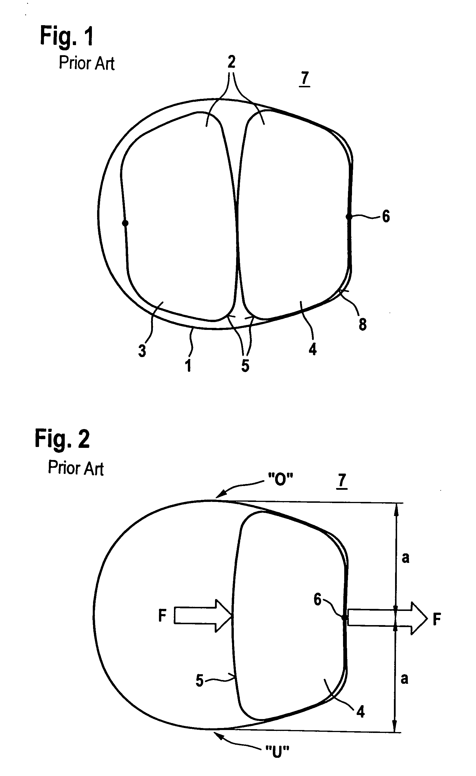
[0039]FIG. 1 shows a schematic representation of a detail of a known plate link chain having two rocker members 2 positioned in an opening 1 of a plate link.

[0040] As can be clearly seen, the rocker member 3 in the drawing plane on the left side can roll off in opening 1 of the link plate, while rocker member 4 is in contact in opening 1.

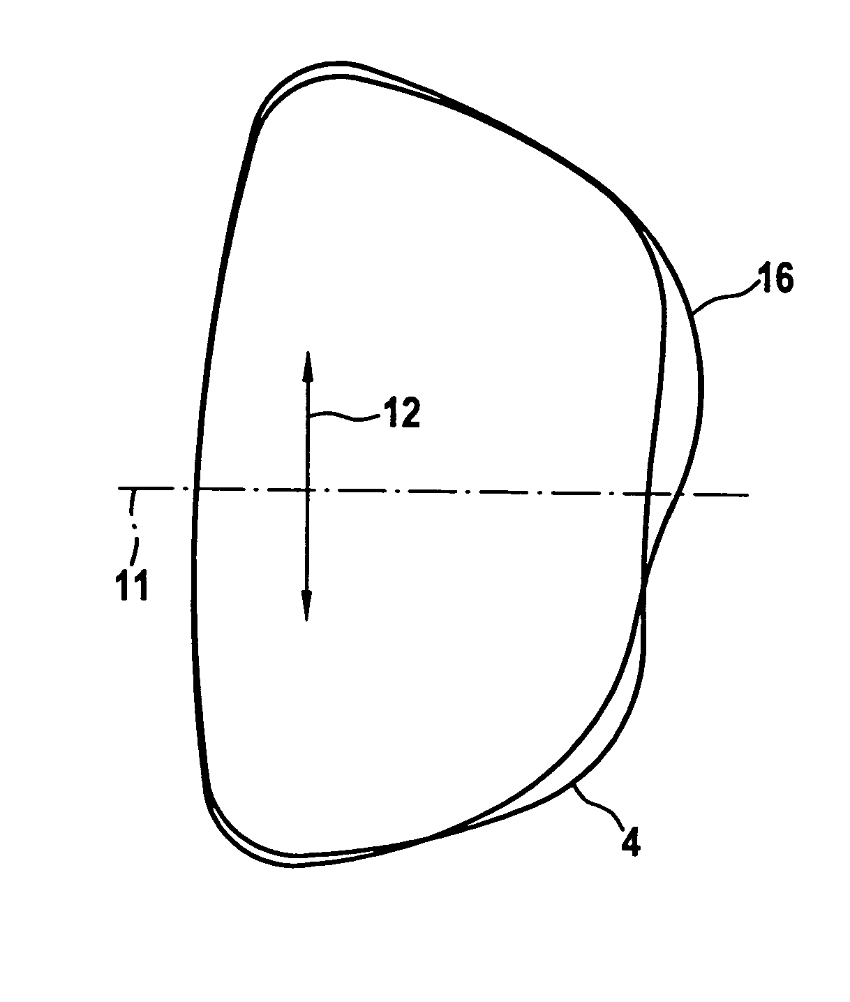
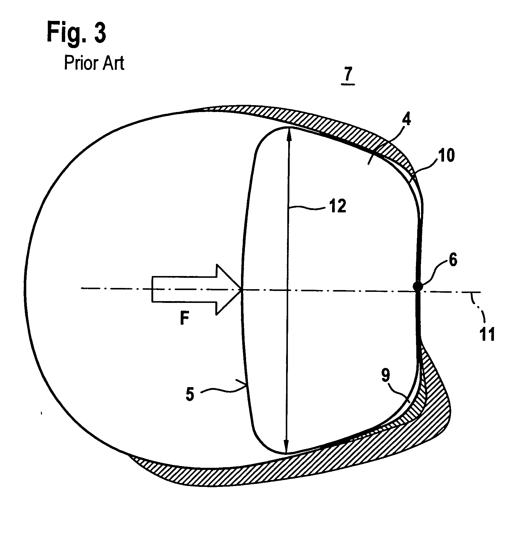
[0041] Positioned between the two rocker members 3, 4 are pitch surfaces 5, at which the rocker members can roll against each other when the plate link chain transitions from an extended position to a curved position, which is the case for example when the running direction is reversed at a pulley. At the pitch surfaces 5 compression forces are transmitted between the rocker members 3, 4, which are transmitted in the illustrated case from rocker member 4 through contact surface 6 into link plate 7. As can be clearly seen, in the case of the known plate link chain only one contact surface 6 is formed on the back 8 of rocker member 4 opposite the pi...


PUM


Abstract

A plate link chain for a motor vehicle drive system. A number of link plates are hingedly connected by pairs of rocker members that extend transversely to the longitudinal direction of the chain. Curved contact surfaces are located on each of the rocker members and link plates, along which contact surfaces the rocker members and link plates contact each other to transmit power. The rocker members also include curved pitch surfaces along which rocker member pairs roll against each other to transmit power. The rocker members are shaped asymmetrically in the height direction and about a cross section plane extending in the longitudinal direction of the chain. Contact surfaces are provided on each of the upper and lower contact surface areas in the height direction of the rocker members.

Description

BACKGROUND OF THE INVENTION [0001] 1. Field of the Invention [0002] The present invention relates to a plate link chain, particularly for a motor vehicle drive system, with a large number of link plates hingedly connected to each other by rocker members, where the rocker members extend transversely to the longitudinal direction of the plate link chain. Located on each of the rocker members and link plates there are curved contact surfaces, along which the rocker members and link plates are in contact with each other to transmit power. Also located on the rocker members are curved pitch surfaces along which the rocker members roll against each other to transmit power. [0003] 2. Description of the Related Art [0004] Such a plate link chain can be a toothed chain, which can be employed, for example, to transfer power in an all-wheel power divider transmission of a motor vehicle, or also, for example, on an auxiliary unit of the internal combustion engine of the motor vehicle. In the na...

Claims


Application Information

Patent Timeline
IPC IPC(8): F16G13/04
CPCF16G13/04F16G5/18
Inventor PICHURA, MICHAELVORNEHM, MARTINSIMONOV, ANTON
Owner SCHAEFFLER TECH AG & CO KG
Why Eureka
Try Eureka