Surgical Staple

a staple and surgical technology, applied in the field of surgical staples, can solve the problems of ineffectiveness, unnecessary damage to the vessel wall, and decrease the compression level between the staple legs, and achieve the effects of increasing the contact area, and increasing the area of compression

Inactive Publication Date: 2007-01-11
ABBOTT CARDIOVASCULAR
View PDF99 Cites 161 Cited by
  • Summary
  • Abstract
  • Description
  • Claims
  • Application Information

AI Technical Summary

Benefits of technology

[0012] The advantage of the invention is that the improved surgical staple delivers a significantly increased area of compression between the staple legs once the staple has been deformed in use. The increased area of compression is achieved by providing the compression portion which tends to increase the contact area between the staple and the tissue against which it is bearing.
[0013] The invention is particularly useful in applications where the staple is permanently implanted inside the body. In such cases it is desirable to minimize the amount of metal which is needed to effect a positive closure. With existing stapler devices a series of staples need to be positioned along the length of the slit or tissue edges being anastomosed. Staples are normally positioned close together as any one staple will only compress a small amount of tissue on either side. Using staples with an improved compression capacity, as provided by this invention, will mean that a significantly lower number of staples is required to close any one incision.
[0014] The invention also has particular relevance in the area of vascular puncture closure. During this percutaneous procedure it is desirable to close the arterial puncture preferably with one staple. Again it is desirable that the staple contains the minimum amount of metal. However, it is important that once delivered the staple has generated enough compression along the length of the slit or hole to prevent any blood leakage. The direction of height of the compression portion normal to the plane of closure of the legs corresponds in use to the direction of length along the incision.

Problems solved by technology

While this method of closing an incision is effective when a series of staples are used along the length of the incision it is less effective when it is desirable to close the opening with the minimum number of staples.
For example for an incision of 5-6 mm in length one round wire staple positioned centrally along the incision is insufficient to effect a closure as the compression due to the staple legs only acts in a limited area towards the center of the incision, leaving the extremities open.
Also in situations where the tissue is soft and friable the narrow staple leg will have a tendency to tear through the tissue as they are bent around the anvil thereby decreasing the level of compression between the staple legs and causing unnecessary damage to the vessel wall.
If the staple legs penetrate into the lumen of the vessel there is the added danger that excessive pressure from the staple gun may cause the vessel to collapse, which can lead to the legs penetrating the opposing vessel wall, i.e. stapling the vessel walls together and blocking the lumen of the vessel.

Method used


Image

  • Surgical Staple
  • Surgical Staple
  • Surgical Staple

Examples


Embodiment Construction

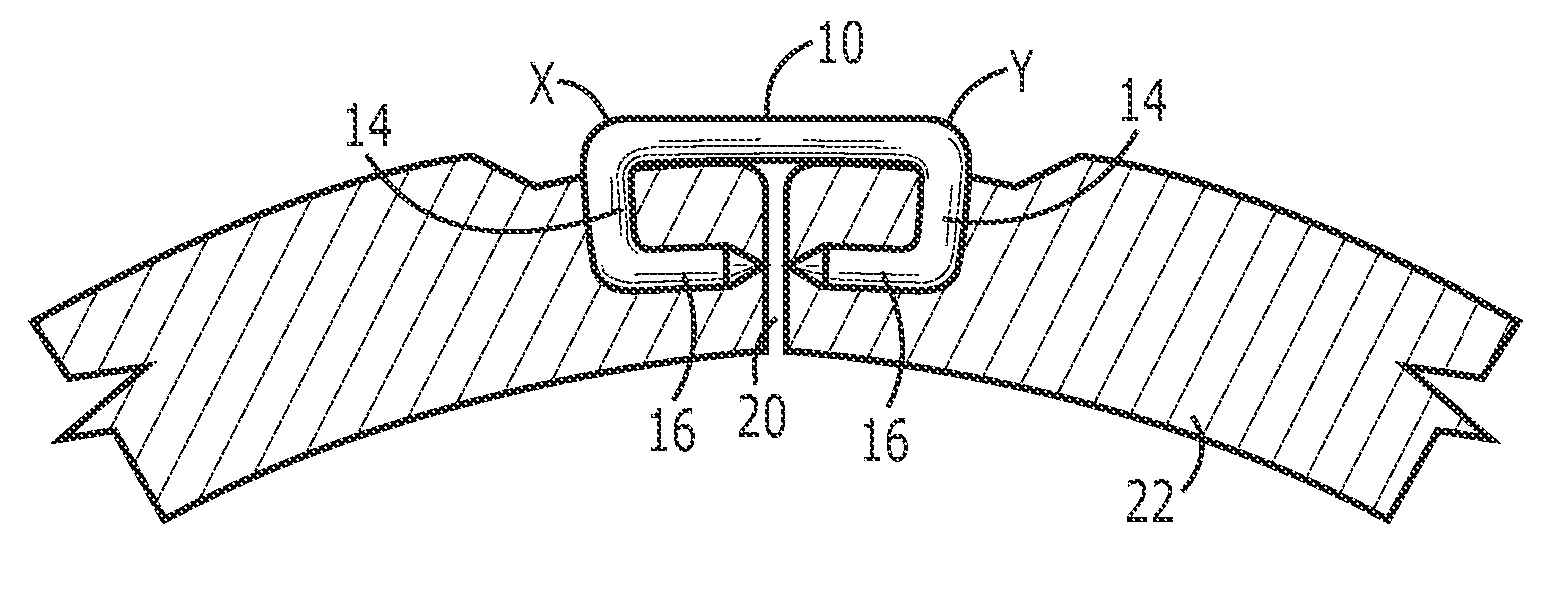
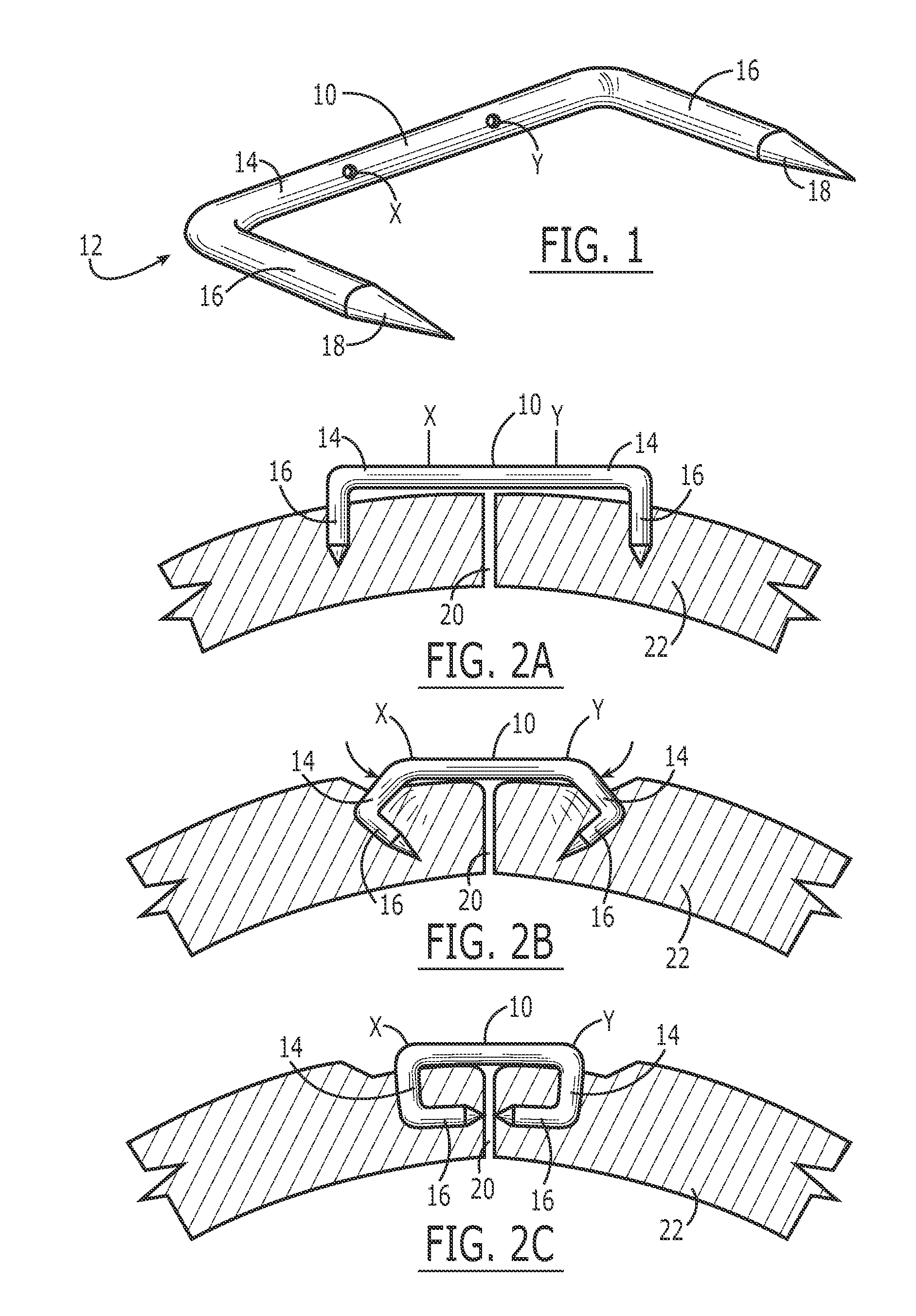
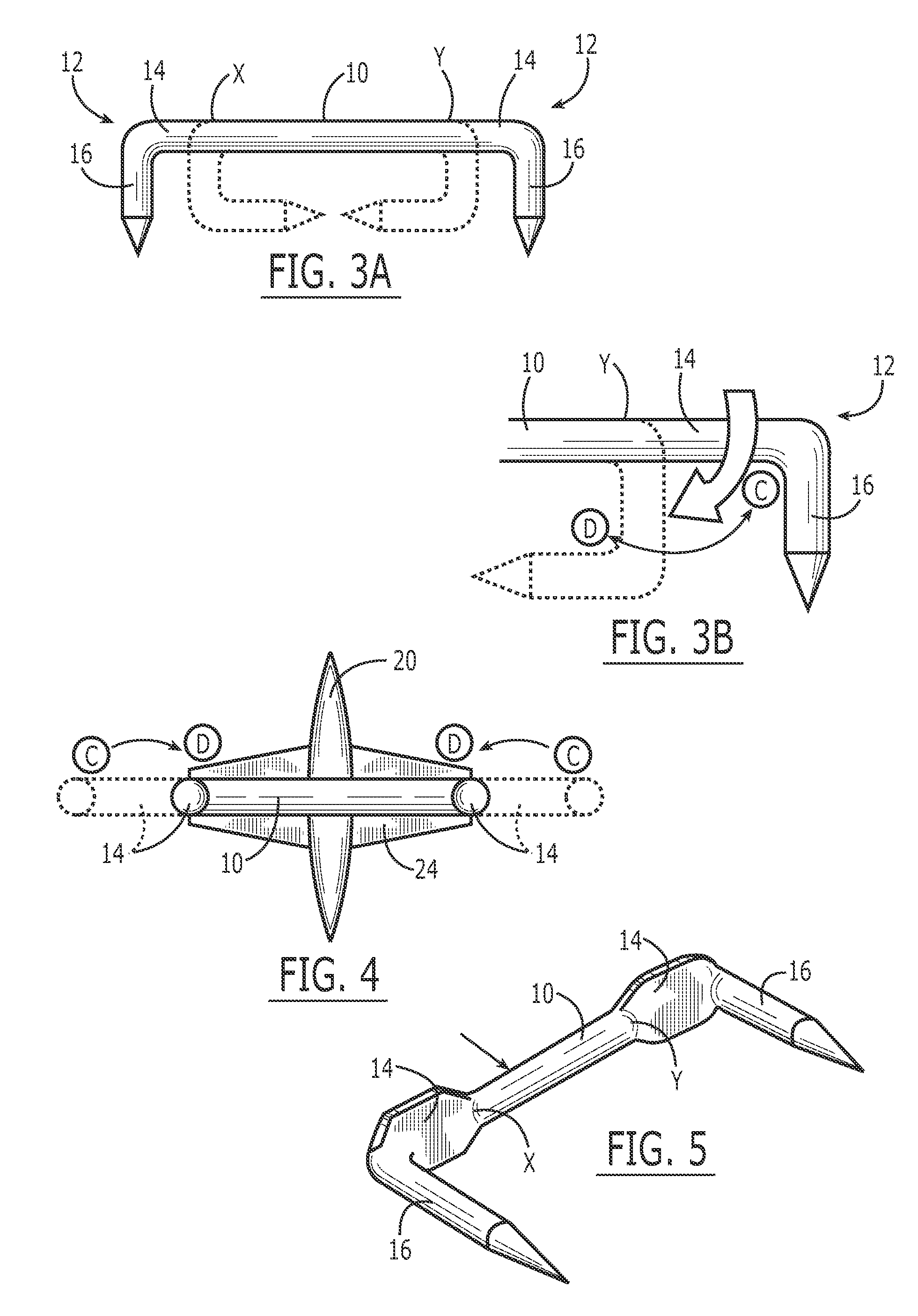
[0027] Referring first to FIG. 1, a conventional round wire surgical staple is of a generally ‘U’-shaped configuration, consisting of a base 10 and a pair of “L”-shaped legs 12 each having a proximal portion 14 forming a linear extension of the base before use (as shown in FIG. 1) and a distal portion 16 projecting substantially perpendicularly from the proximal portion.

[0028] The free ends 18 of the staple legs are generally sharpened so as to ensure easy tissue penetration. In addition to penetrating the tissue the staple is also formed in use, to bring the free ends of the legs together and thereby hold closed a wound. By forming the staple, the staple is transformed from a generally “U”-shaped configuration to a generally rectangular shaped configuration during the delivery process. This occurs by bending the legs 12 through 90° relative to the base 10 of the staple at the point where the proximal portions of the legs meet the base (known as the bend points and denoted as point...


PUM


Abstract

A generally U-shaped surgical staple comprises a base 10 and a pair of generally “L”-shaped legs 12 extending substantially perpendicularly from opposite ends of the base respectively. The legs 12 in use of the staple are bent through approximately 90° relative to the base. To effect a greater compression of the stapled tissue the legs include a penetrative portion 16 adjacent the tip and a compressive structure 30 which, due to its increased height relative to that of the penetrative portion, spreads the compressive forces of the staple further along the length of the incision being closed. The compressive portion also provides a depth stop to avoid the tip penetrating too deeply into the tissue in which it is deployed.

Description

CROSS REFERENCE TO RELATED APPLICATIONS [0001] This application is a continuation of U.S. patent application Ser. No. 10 / 240,183 filed on Jan. 22, 2003 and entitled “Surgical Staple” (now U.S. Pat. No. 7,108,709), which is a continuation of International Application PCT / IE02 / 00078, filed on Jun. 4, 2002, entitled “Surgical Staple,” which claims priority to Irish Application No. S2001 / 0547, filed on Jun. 7, 2001. The complete disclosures of these applications are hereby incorporated herein by reference for all purposes.FIELD OF THE INVENTION [0002] This invention relates to a surgical staple. BACKGROUND OF THE INVENTION [0003] Staples have been used in general surgery for many years, mainly for anastomosing tissue. Examples include skin staplers used to close a skin incision in place of the standard manual suturing process, and end-to-end and end-to-side bowel stapling instruments which are generally one shot devices used during bowel reconstruction procedures. [0004] The staples use...

Claims


Application Information

Patent Timeline
Patent Type & Authority Applications(United States)
IPC IPC(8): A61B17/08A61B17/10A61B17/064A61B17/115
CPCA61B2017/0641A61B17/0644
Inventor CUMMINS
Owner ABBOTT CARDIOVASCULAR
Why Eureka
Try Eureka