Coronary sinus approach for repair of mitral valve regurgitation

a coronary sinus and mitral valve technology, applied in the field of medical devices, can solve the problems of complex procedures, many risks, and high cost, and achieve the effects of reducing the risk of complications, and improving the quality of li

Active Publication Date: 2007-01-11
MEDTRONIC VASCULAR INC
View PDF21 Cites 226 Cited by
  • Summary
  • Abstract
  • Description
  • Claims
  • Application Information

AI Technical Summary

Problems solved by technology

Valve insufficiency and regurgitation is a potentially grave health issue that can lead to cardiac dysfunction.
These procedures are complex, time consuming, and involve many risks attendant with open cardiac surgery.
Complications may occur, and recovery time may be significant.
However, the placement of knotted sutures through a catheter can be very difficult and time consuming.
Artificial heart valves for temporary use are known in the art, but present certain problems.
Some designs are complex, requiring alternating the inflation and deflation of balloons to alternately block and permit flow.
Such designs require complex sensing and control systems.
Other designs fail to provide access for tools that must reach the valve site for removal of the native valve and placement of the prosthetic valve.
One drawback to these implanted devices is that the size and shape of these devices often impede the flow of blood through the coronary sinus.

Method used


Image

  • Coronary sinus approach for repair of mitral valve regurgitation
  • Coronary sinus approach for repair of mitral valve regurgitation
  • Coronary sinus approach for repair of mitral valve regurgitation

Examples


Embodiment Construction

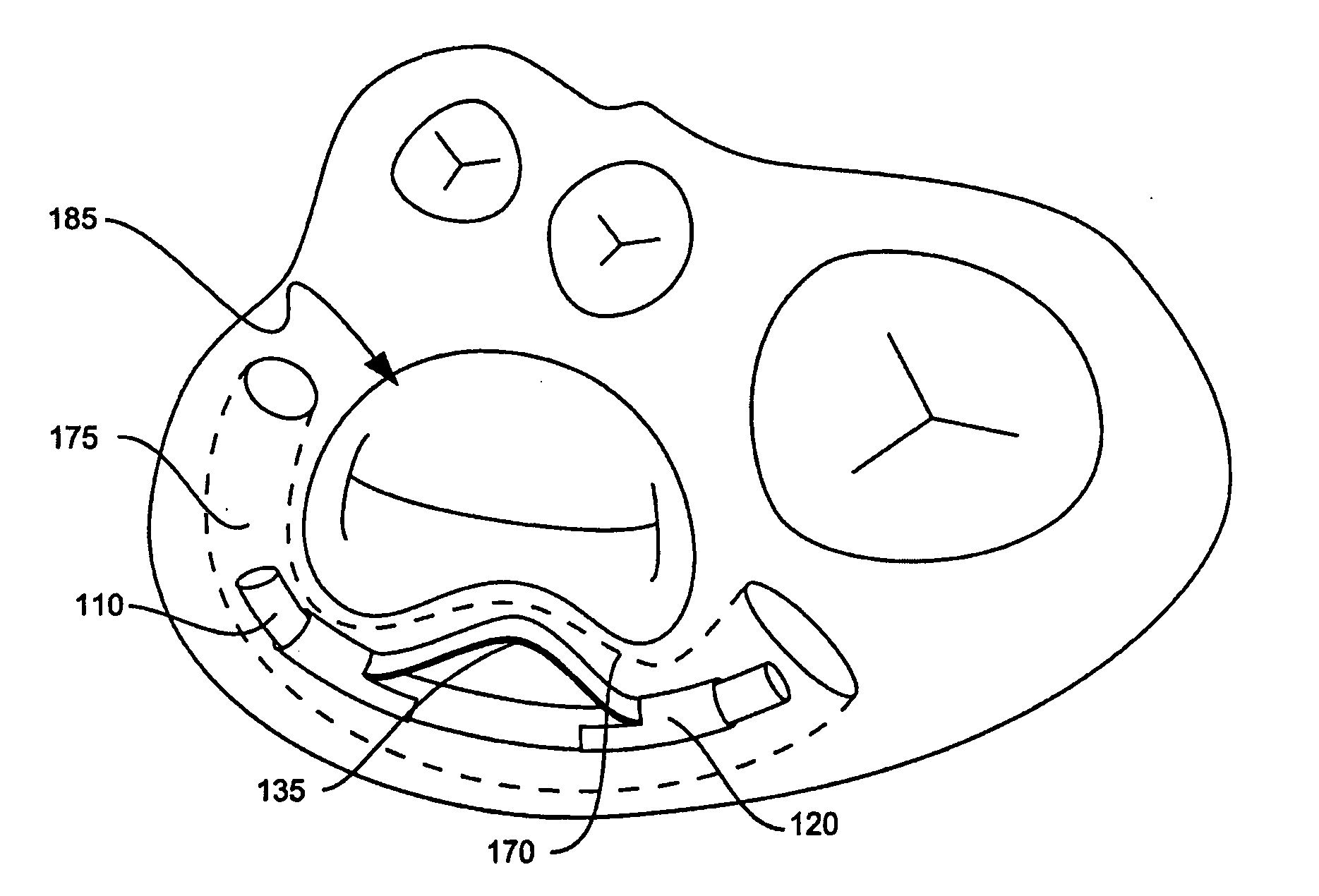
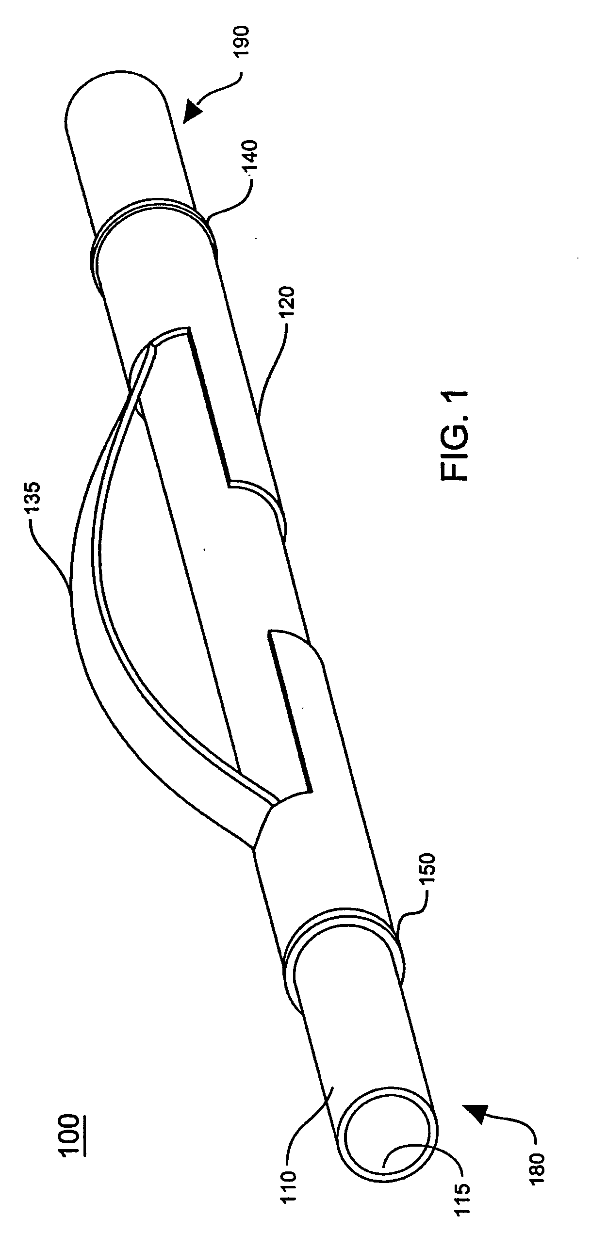
[0022]FIG. 1 illustrates a perspective view of one embodiment of a treatment device 100 for reducing valve regurgitation. Treatment device 100 includes an elongated tubular compression device 120 coaxially carried upon tubular member 110. Tubular member 110 includes central lumen 115, locking mechanism 140 and distal stop member 150. Locking mechanism 140 is located adjacent proximal portion 190 of tubular member 110. Distal stop member 150 is located adjacent distal portion 180 of tubular member 110. The terms “distal” and “proximal” are used herein with reference to the treating clinician during deployment of the device; “Distal” indicates a portion distant from, or a direction away from the clinician and “proximal” indicates a portion near to, or direction towards the clinician. Throughout the following description like elements will have like reference numbers as those of FIG. 1.

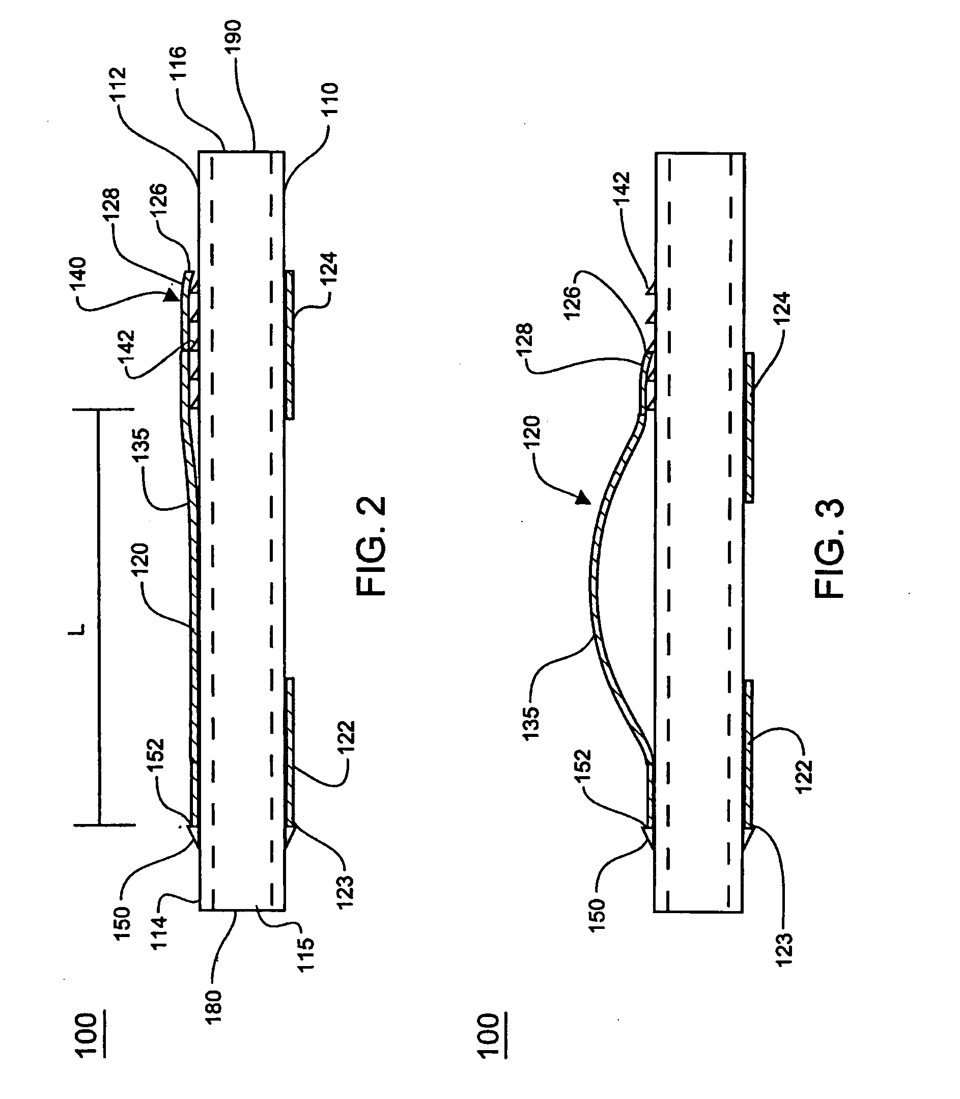
[0023] Referring to FIG. 2, another embodiment of a treatment device for cardiac valves is generally...


PUM


Abstract

A device and method for treating cardiac valve regurgitation. The device includes a tubular member including a lumen there through and a locking mechanism and a compression device carried on the tubular member. The compression device is transformable to a compression configuration in response to axial displacement and is locked in the compression configuration by the locking mechanism. The method includes positioning the compression device adjacent a cardiac valve and applying an axial displacement to the compression device to transform the compression device into a compression configuration and locking the compression device in the compression configuration to apply a compressive force to the cardiac valve.

Description

TECHNICAL FIELD [0001] The technical field of this disclosure is medical devices, particularly for treating mitral valve regurgitation. BACKGROUND OF THE INVENTION [0002] Valve insufficiency and regurgitation is a potentially grave health issue that can lead to cardiac dysfunction. Mitral valve insufficiency may comprise a valve that does not completely shut and affect the seal between the left ventricle and the left atrium. Historically, such a condition necessitated surgical intervention. [0003] Surgical repair of mitral valve insufficiency historically involved the use of a stemotomy or a similar invasive procedure. After performing a stemotomy, the patient's heart would be stopped while the surgeon transected the chambers of the heart to gain access to the mitral valve. Upon attaining access to the mitral valve, the surgeon could then repair the valve by an annuloplasty, or suturing the valve. These procedures are complex, time consuming, and involve many risks attendant with op...

Claims


Application Information

Patent Timeline
Patent Type & Authority Applications(United States)
IPC IPC(8): A61F2/24
CPCA61F2/2451
Inventor RAFIEE, NASSERDOUK, NAREAKCRITTENDEN, JAMES F.
Owner MEDTRONIC VASCULAR INC
Why Eureka
Try Eureka