Cylinder liner, cylinder block, and method for manufacturing cylinder liner
a technology of cylinder block and cylinder liner, which is applied in the direction of manufacturing tools, machines/engines, engines without rotary main shafts, etc., can solve the problems of insufficient bonding between the cylinder liner and the metal forming the cylinder block, the cylinder block does not support the cylinder liner in sufficient degree, and the roundness of the cylinder bore is difficult to maintain in a satisfactory state, etc., to achieve sufficient roundness of the cylinder bore and the cylinder lin
- Summary
- Abstract
- Description
- Claims
- Application Information
AI Technical Summary
Benefits of technology
Problems solved by technology
Method used
Image

Examples
first embodiment
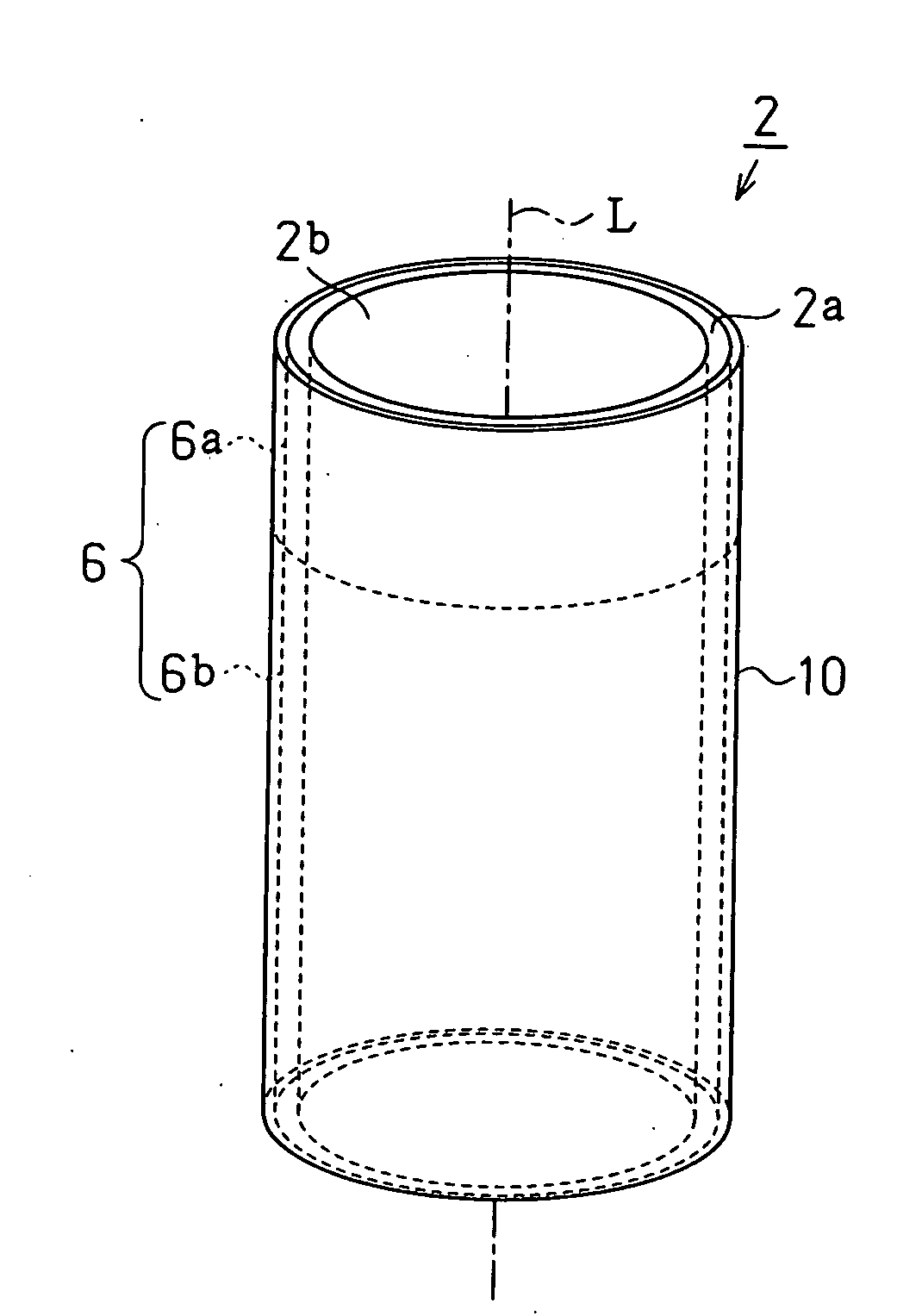
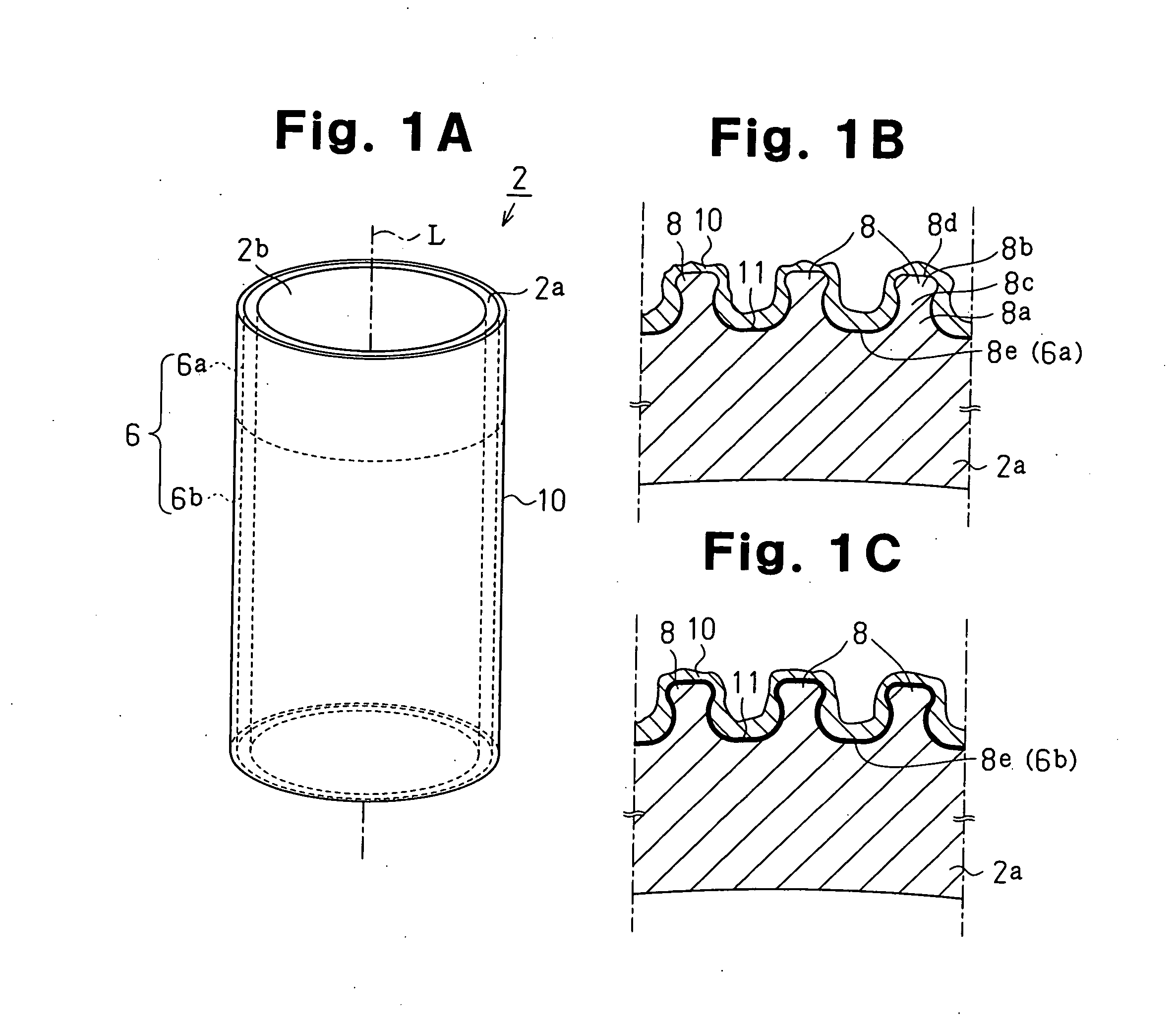
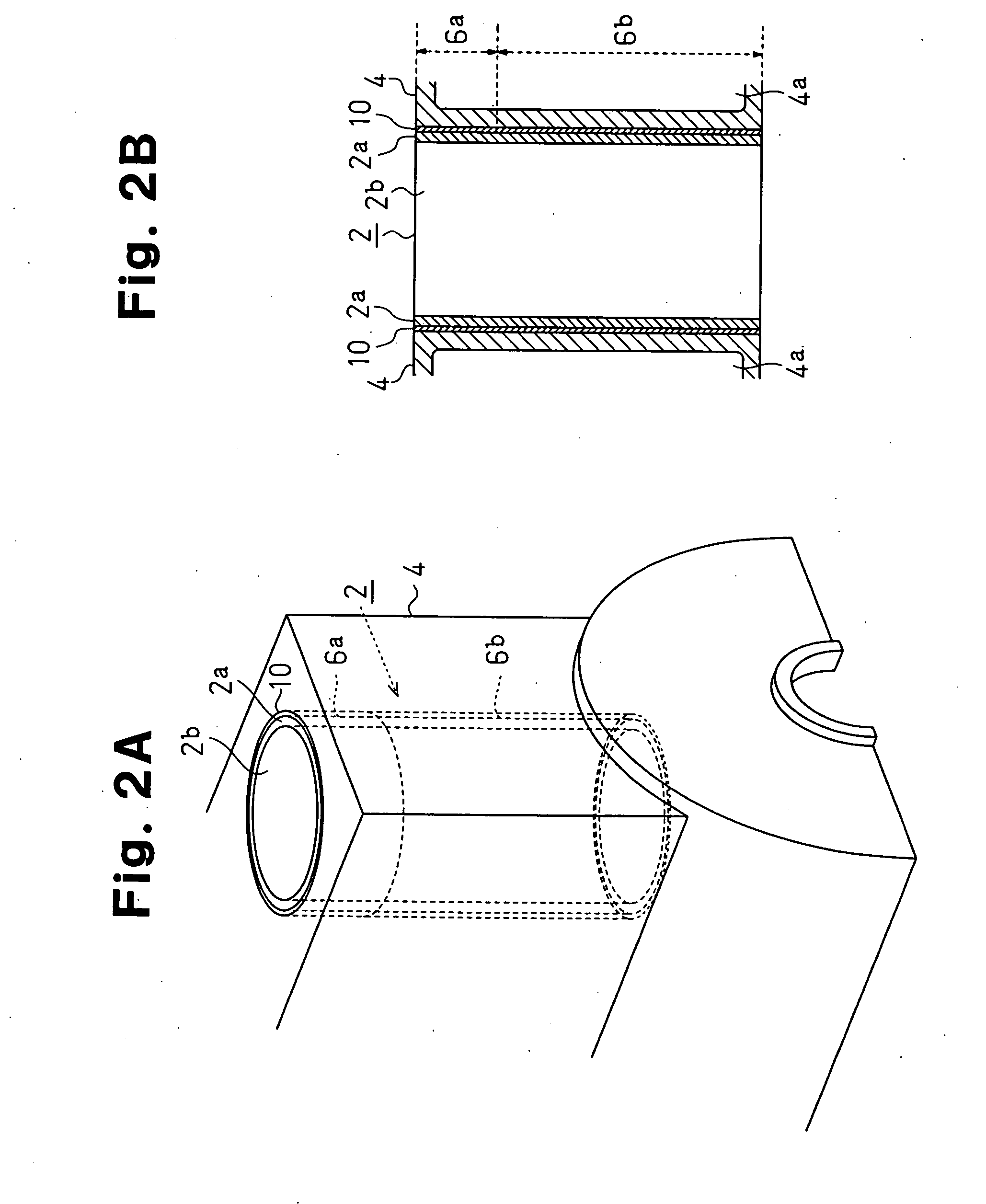
[0035] A first embodiment of the present invention will now be described with reference to FIGS. 1A to 2B. FIG. 1A is a perspective showing a cylinder liner 2 according to the present invention. FIG. 1B is an enlarged cross-sectional view showing the upper portion of the cylinder liner 2. FIG. 1C is an enlarged partial cross-sectional view showing the lower portion of the cylinder liner 2. FIG. 2A is a partial perspective view showing a cylinder block 4 using the cylinder liner 2. FIG. 2B is a partial cross-sectional view showing the cylinder block 4 using the cylinder liner 2.
[0036]2>
[0037] A main body 2a of the cylinder liner 2 shown in FIGS. 1A to 1C is made of cast iron. A plurality of bottleneck-shaped projections 8 are formed on the outer surface 6 of the cylinder liner main body 2a (hereinafter referred to as the “liner outer surface 6”). The projections 8 have the features listed below.
[0038] (1) Each projection 8 has a portion that is narrowest (narrowed portion 8c) at a ...
second embodiment
[0098] In the second embodiment, steps I and J, which are shown in FIGS. 10 to 13, are performed in lieu of steps G and H of the first embodiment.
[Step I]
[0099] As shown in FIG. 10, a roughening process is evenly performed on the entire liner outer surface 106 of the cylinder liner main body 102a, which is formed through steps A to F in the same manner as the first embodiment, with a roughening device (the blast processing device 32 or other blast processing devices or a water jet device) 132.
[Step J]
[0100] As shown in FIGS. 11 and 12, in sub-steps J-1 and J-2, a spraying device entirely sprays (wire sprays or sprays powders such as plasma or HVOF) the liner outer surface 106 of the cylinder liner main body 102a, which has undergone the roughening process of step I. The spraying material is an aluminum spraying material of aluminum or an aluminum alloy.
[0101] The sub-steps J-1 and J-2, which are the procedures for forming a sprayed layer 116, will now be described.
[0102] [Sub-...
third embodiment
[0113] In the third embodiment, during sub-step J-1 of the second embodiment, the partial sprayed layer 112 and the fume deposit layer 114 are formed in a state in which the air around the cylinder liner main body 102a is drawn toward the lower region 106b from the upper region 106a by a discharge duct (corresponding to suction device) as shown in FIG. 15. This ensures that the fumes 133c evenly contact the lower region 106b. The other steps are the same as those in the second embodiment.
[0114]
[0115] To check changes in the adhesiveness of the sprayed layer 116 that depends on the presence of the fume deposit layer 114 of the present embodiment, a cylinder liner Jc that does not have projections 8 was prepared. The same process as the spraying process performed on the lower region 106b was performed through sub-step J-1 shown in FIG. 15 and sub-step J-2 of the second embodiment shown in FIG. 12, the fume deposit layer 114 and the sprayed layer 116 were formed on the cylinder liner ...
PUM
| Property | Measurement | Unit |
|---|---|---|
| Length | aaaaa | aaaaa |
| Length | aaaaa | aaaaa |
| Length | aaaaa | aaaaa |
Abstract
Description
Claims
Application Information
 - Generate Ideas
- Intellectual Property
- Life Sciences
- Materials
- Tech Scout
- Unparalleled Data Quality
- Higher Quality Content
- 60% Fewer Hallucinations
Browse by: Latest US Patents, China's latest patents, Technical Efficacy Thesaurus, Application Domain, Technology Topic, Popular Technical Reports.
© 2025 PatSnap. All rights reserved.Legal|Privacy policy|Modern Slavery Act Transparency Statement|Sitemap|About US| Contact US: help@patsnap.com