Direct drive generator and wind turbine

a direct drive generator and wind turbine technology, applied in the direction of magnetic circuit rotating parts, greenhouse gas reduction, magnetic circuit shape/form/construction, etc., can solve the problems of difficult large size of the largest element to be transported, and large dead load etc., to achieve simplified transport of direct drive generators to the site of erection

Active Publication Date: 2009-05-28
SIEMENS GAMESA RENEWABLE ENERGY AS
View PDF12 Cites 27 Cited by
  • Summary
  • Abstract
  • Description
  • Claims
  • Application Information

AI Technical Summary

Benefits of technology

[0011]It is therefore an object of the present invention to provide a generator as initially mentioned in such a way, that in particular the transport ...

Problems solved by technology

The large outer diameter makes the transport of the direct drive generator difficultly and the heavy dead load of the direct drive generator involves further difficulties e.g. concerning the replacement for repair by occurred breakdowns.
A further difficulty arises in the normal configuration of a wind turbine with a direct drive generator, where the direct drive generator is arranged between the wind turbine rotor and the tower in order to yield a compact machine construction.
However, this construction requires a stator housing as such having relatively large outer dimensions.
The drawb...

Method used


Image

  • Direct drive generator and wind turbine
  • Direct drive generator and wind turbine
  • Direct drive generator and wind turbine

Examples


Embodiment Construction

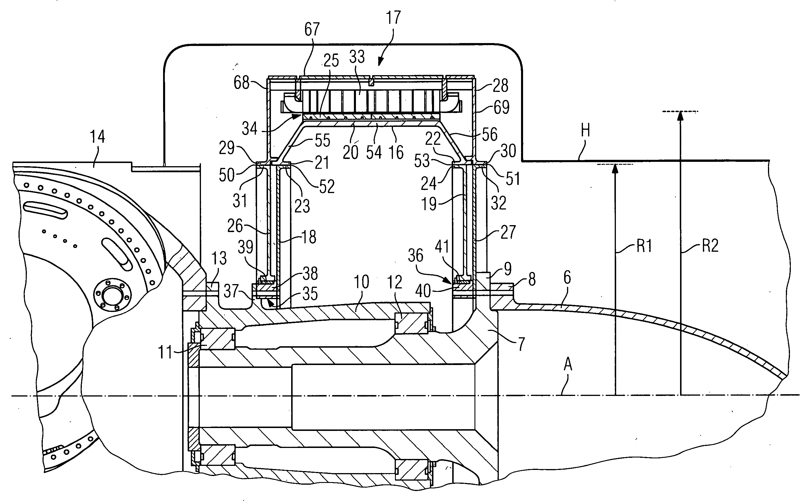
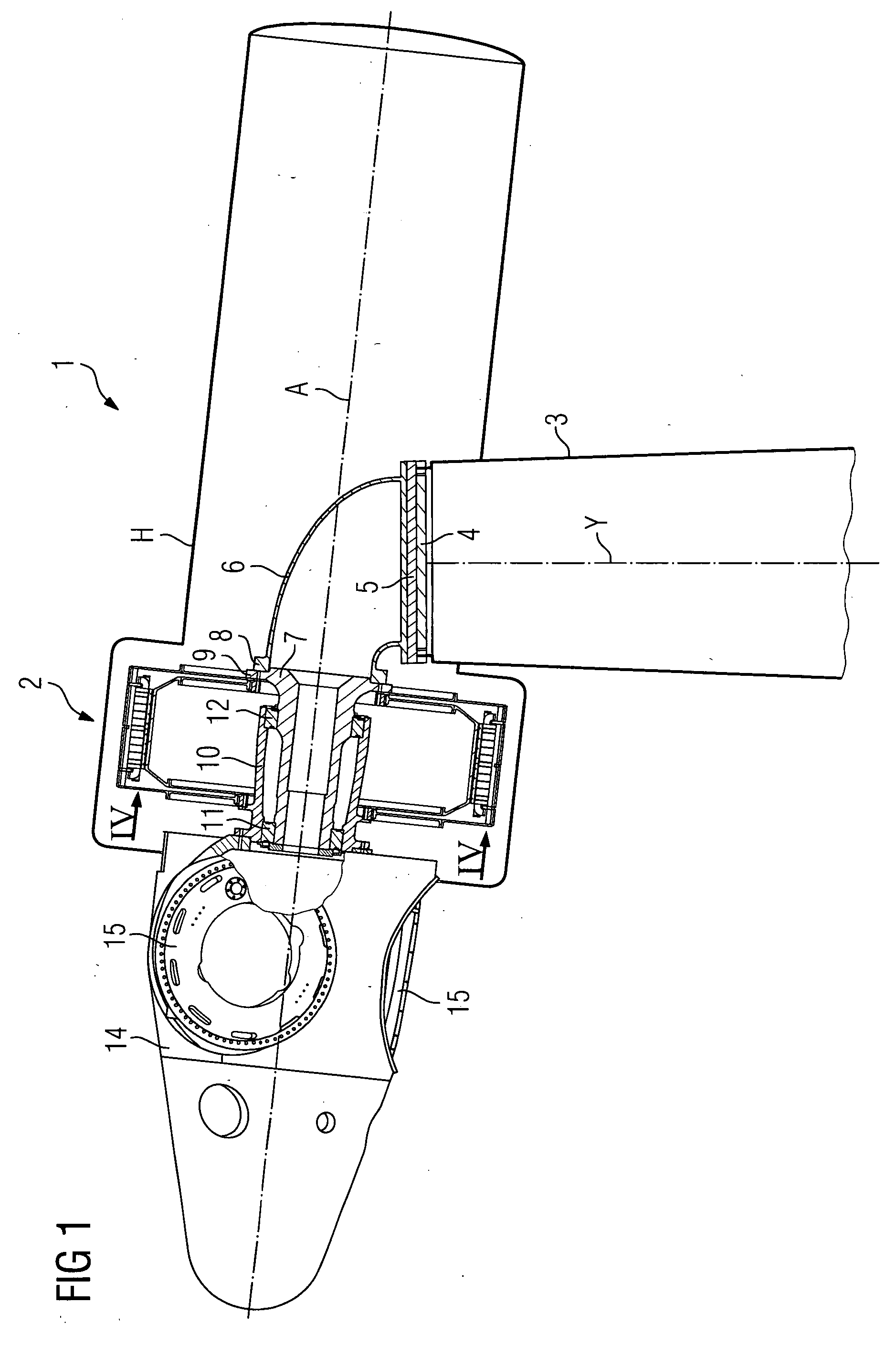
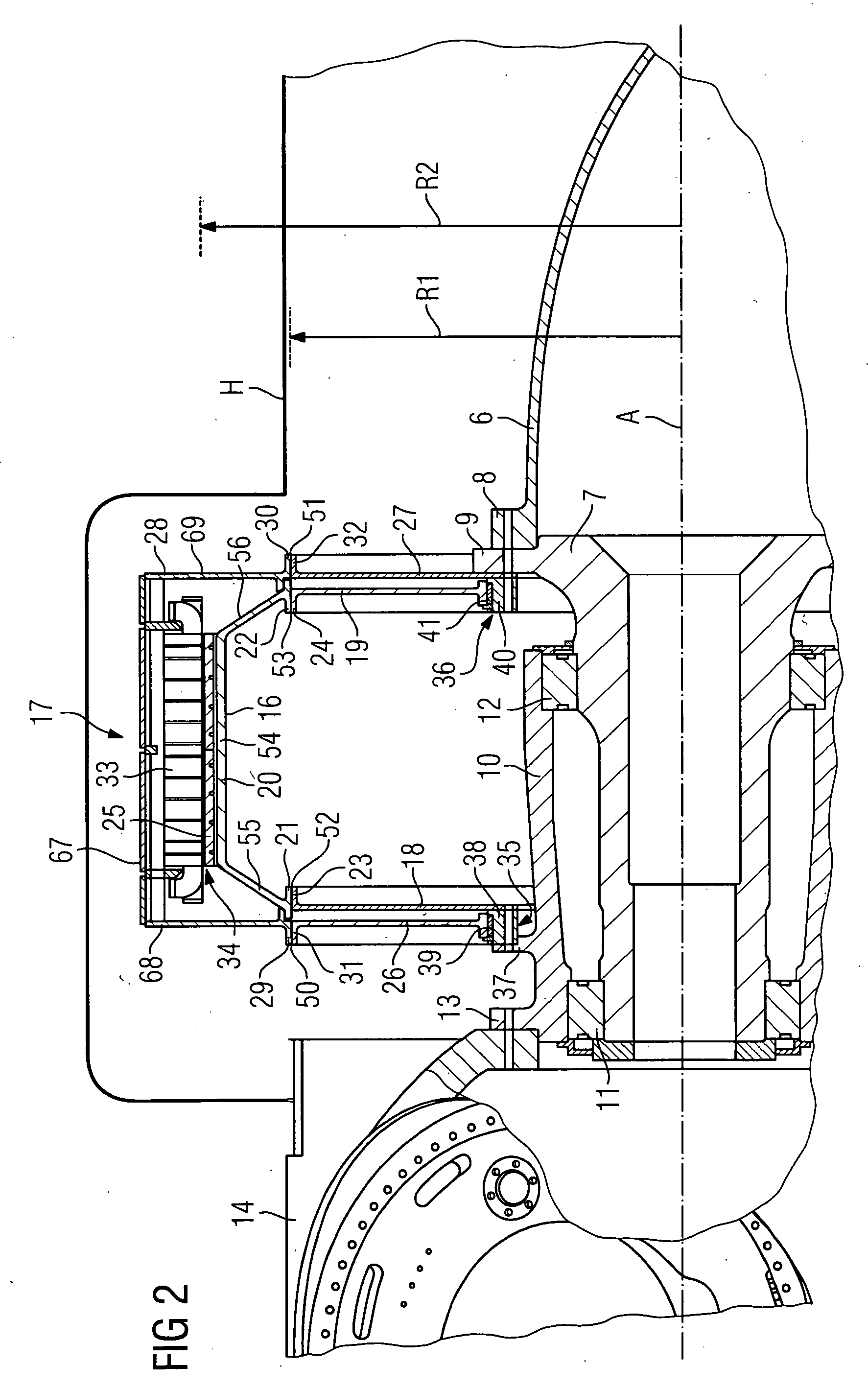
[0033]FIG. 1 shows schematically a first embodiment of an inventive wind turbine 1 comprising an inventive direct drive or directly driven generator 2 which is arranged on the upwind side of a tower 3 of the wind turbine 1.

[0034]A tower flange 4 is arranged on the top of the tower 3. A retaining arrangement is arranged on the tower flange 4 comprising in case of the present embodiment of the invention a bedplate 5, a retaining frame in form of a retaining arm 6 and a stationary or fixed hollow shaft 7. The bedplate 5 is attached to the tower flange 4. The wind turbine 1 comprises in a not explicitly shown manner a yaw system for turning the bedplate 5 of the wind turbine 1 around the centre axis Y of the tower 3 together with the other components of the wind turbine 1 which are directly or indirectly attached to the bedplate 5.

[0035]The retaining arm 6 is on its base side directly arranged on the bedplate 5. On the other side the retaining arm 6 comprises a flange 8. The stationary ...


PUM


Abstract

The invention concerns a direct drive or directly driven generator for a wind turbine comprising a stator having at least one stator element for power generation and a rotor pivotable around a centre axis of the generator having at least one rotor element for power generation, the generator having an air gap between the stator element and rotor element, wherein the stator comprises a front and a rear ring-shaped supporting element and stator segments being attached to the front and rear ring-shaped supporting elements of the stator, wherein junctions between the front and rear ring-shaped supporting elements of the stator and stator segments are located substantially at a radius in relation to the centre axis of the generator which is smaller than the radius of the air gap between the stator element and rotor element. Furthermore the invention concerns a wind turbine comprising such a direct drive generator.

Description

CROSS REFERENCE TO RELATED APPLICATIONS[0001]This application claims priority of European application No. 07022882.0 filed Nov. 26, 2007, which is incorporated by reference herein in its entirety.FIELD OF THE INVENTION[0002]The invention relates to a direct drive or directly driven generator as well as to a wind turbine comprising a direct drive generator.BACKGROUND OF THE INVENTION[0003]In principle there are two main types of wind turbines in view of the drive configuration of a wind turbine. The first type of a wind turbine is the more classical type of a wind turbine comprising a gearbox arranged between a main shaft and a generator of the wind turbine. The second type of a wind turbine is a gearless type, whereat the gearbox and the conventional generator are substituted by a multipolar generator, a so called direct drive or directly driven generator. Such a direct drive generator can be made as a synchronous generator with winded rotor or with permanent magnets attached to the...

Claims


Application Information

Patent Timeline
IPC IPC(8): F03D9/00H02K1/18
CPCF03D9/002F03D9/021F03D11/00F05B2220/7066H02K1/185H02K7/1838H02K15/16H02K21/14H02K2213/09Y02E10/722Y02E10/725H02K1/30F03D9/11F03D9/25F03D13/10F03D13/20F03D80/00F03D80/70Y02E10/72Y02E10/728Y02E70/30
Inventor STIESDAL, HENRIK
Owner SIEMENS GAMESA RENEWABLE ENERGY AS
Why Eureka
Try Eureka