Launch vehicle crew escape system

a technology for escaping systems and launch vehicles, which is applied in the field of spacecraft launch escape systems, can solve the problems of not being able to provide 1 g, the upper stage engine has too little thrust to provide acceleration, and the normal upper stage is not able to provide enough thrust for a launch abort system, so as to achieve the effect of increasing the acceleration it can provid

Inactive Publication Date: 2007-01-18
BUEHLER DAVID BENJAMIN
View PDF21 Cites 22 Cited by
  • Summary
  • Abstract
  • Description
  • Claims
  • Application Information

AI Technical Summary

Benefits of technology

[0015] The current invention solves this problem by having the upper stage oxidizer tanks mostly empty at launch. The oxidizer is stored temporarily inside the next lower stage or in the interstage region. It is only transferred to the upper stage after the region where high-escape accelerations are needed. This means that during the time-frame where the high-acceleration launch escape will be needed, the upper stage is a fraction of its normal mass. For example, when hydrogen peroxide is used as the oxidizer, over 75% of the fully-loaded wet mass of the upper stage and payload is the hydrogen peroxide. Thus, with the oxidizer tank mostly empty, even though the upper stage main engine is producing the same amount of thrust, it is being used to accelerate a much lower mass thus greatly increasing the accelerations it can provide. Accelerations as high as 4 Gs may be possible using this system which is adequate for launch escape needs.
[0016] This system for launch escape has many advantages over the prior art solid propellant launch escape tower concept.

Problems solved by technology

Typically, upper stage engines have too little thrust to provide acceleration that would be needed to lift a capsule away from the first stage of a vehicle under high-dynamic pressures (and especially if the first stage is still firing).
Most are not capable of providing 1 G at the start of their burn. launch escape systems usually need to generate much higher thrusts—at least 2-3 Gs of acceleration, so a normal upper stage is not able to provide enough thrust for a launch abort system.

Method used


Image

  • Launch vehicle crew escape system
  • Launch vehicle crew escape system
  • Launch vehicle crew escape system

Examples


Embodiment Construction

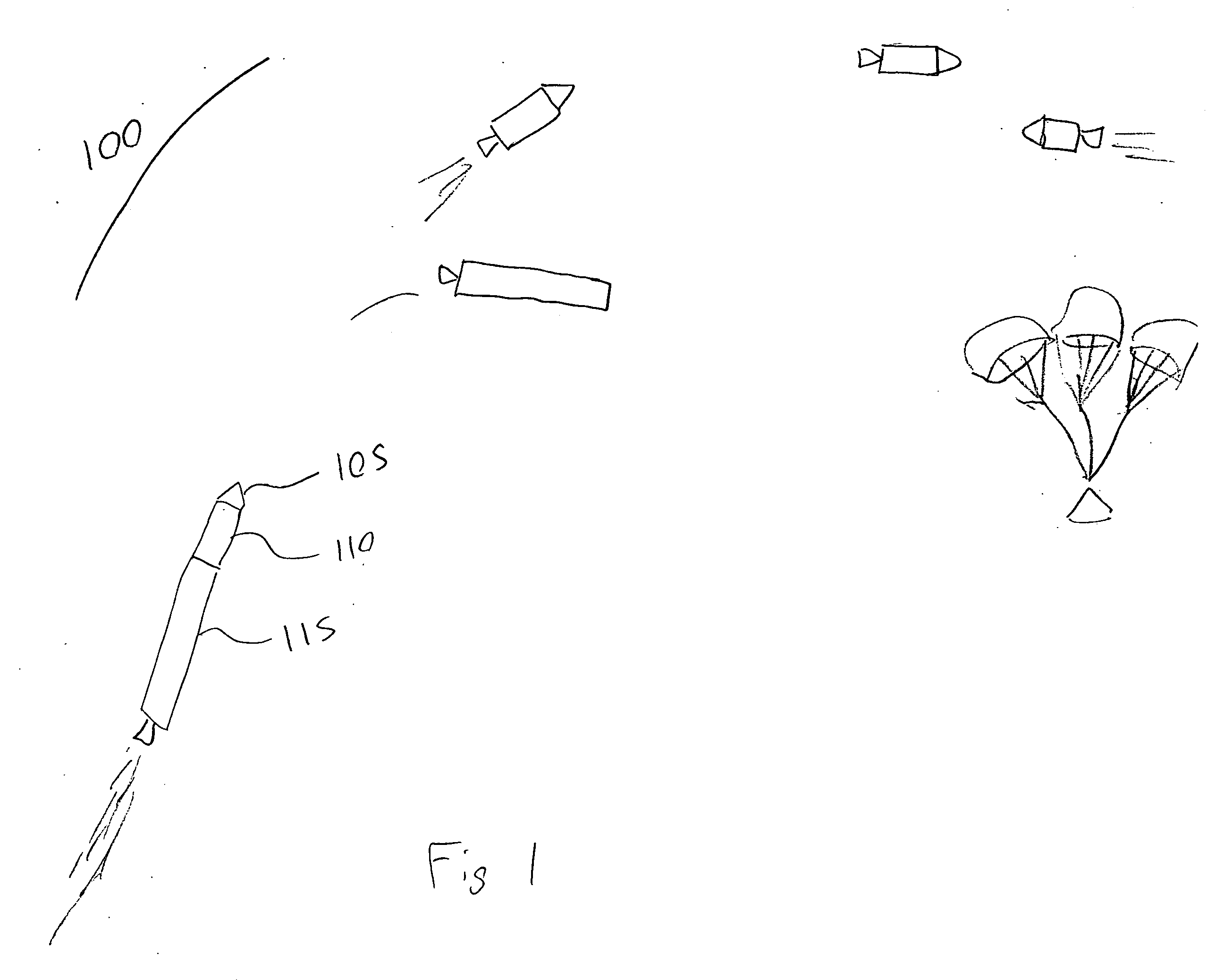
[0029]FIG. 1 is a pictorial sequence of a successful launch and reentry. As depicted, a successful launch and reentry sequence (100) under normal conditions is shown for a recoverable crew or cargo capsule. The capsule (105) is releasably connected to the upper stage (110), and the upper stage is releasably connected to the lower stage (115). On the launch pad, the majority of the oxidizer for upper stage (110) is stored in lower stage upper stage oxidizer reservoir (230). Near burnout of the lower stage (115), that oxidizer is transferred to the upper stage (110). After lower stage burnout, the stages separate and the upper stage (110) puts the capsule (105) into orbit.’

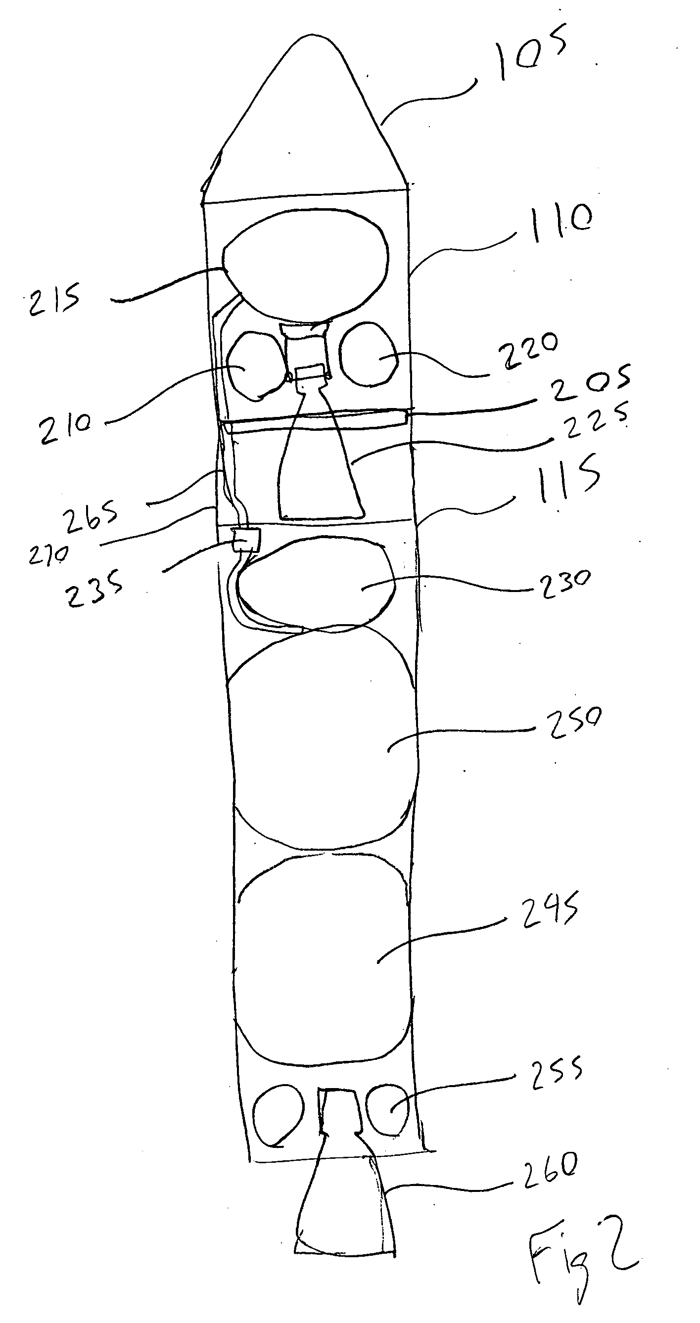
[0030]FIG. 2 is a cutaway schematic of a two stage launch vehicle equipped with the crew escape system. As depicted, the crew or cargo capsule (105) is located on top of the upper stage (110) and is connected to it by a release system (205). The upper stage (110) contains a fuel tank (210), oxidizer tank (215), pres...


PUM


Abstract

A launch vehicle upper-stage escape system is described that allows a crew capsule or a payload capsule to be safely and rapidly separated from a launch vehicle in the event of an emergency using the upper stage main engine for propulsion. During the initial portion of the flight the majority of the propellant mass for the upper stage is stored in the lower stage. This minimizes the mass of the upper stage allowing the upper stage main engine to provide sufficient acceleration to lift the capsule off of the launch vehicle and to move the capsule away from the launch vehicle to a safe distance with sufficient speed in the event of an emergency. It can also be used to lift the crew or payload capsule to a sufficient height for recovery systems to be employed successfully in the event of an on-pad or low-altitude launch emergency.

Description

[0001] This application claims the benefit of provisional application 60 / 600,570 filed Aug. 11, 2004 entitled “Launch Vehicle Crew Escape System”. [0002] It also references USPTO disclosure document number 548114 filed Mar. 2, 2004, entitled “Launch Vehicle Crew Escape System”.BACKGROUND OF THE INVENTION [0003] 1. Field of the Invention [0004] This invention is in the field of spacecraft launch escape systems. [0005] 2. Description of Related Art [0006] Crew escape systems are used to propel the crew to safety in the event of a launch vehicle failure such as an explosion or an engine failure. The escape system is also used to propel the crew to a sufficient altitude and distance for a recovery system (such as parachutes) to function correctly. [0007] In the past, such dangers have been dealt with using either ejection seats or launch escape towers. Launch escape towers are by far more common and have been used on US, Russian, and now Chinese manned launches. Launch escape towers hav...

Claims


Application Information

Patent Timeline
Patent Type & Authority Applications(United States)
IPC IPC(8): B64G1/60
CPCB64G1/402B64G1/60B64G1/52
Inventor BUEHLER, DAVID BENJAMIN
Owner BUEHLER DAVID BENJAMIN
Why Eureka
Try Eureka