Projecting device
a projecting device and projector technology, applied in the field of projecting devices, can solve the problems of difficult to maintain the aspect ratio, the degree of freedom in selecting the magnification of each projective optical system is restricted, and the correction of the aspect ratio becomes almost impossible, so as to facilitate the maintenance of the aspect ratio and reduce the thickness of the projecting device. , the effect of high degree of freedom
- Summary
- Abstract
- Description
- Claims
- Application Information
AI Technical Summary
Benefits of technology
Problems solved by technology
Method used
Image
Examples
first example
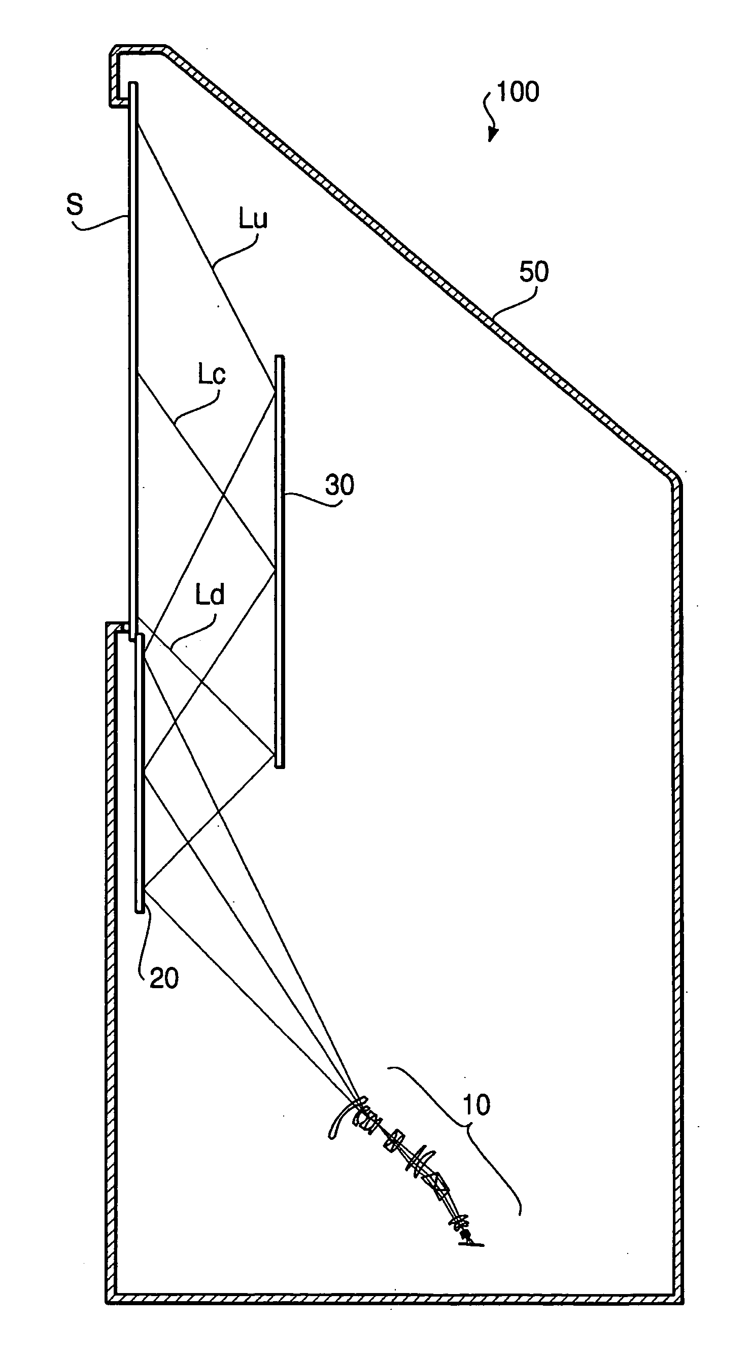
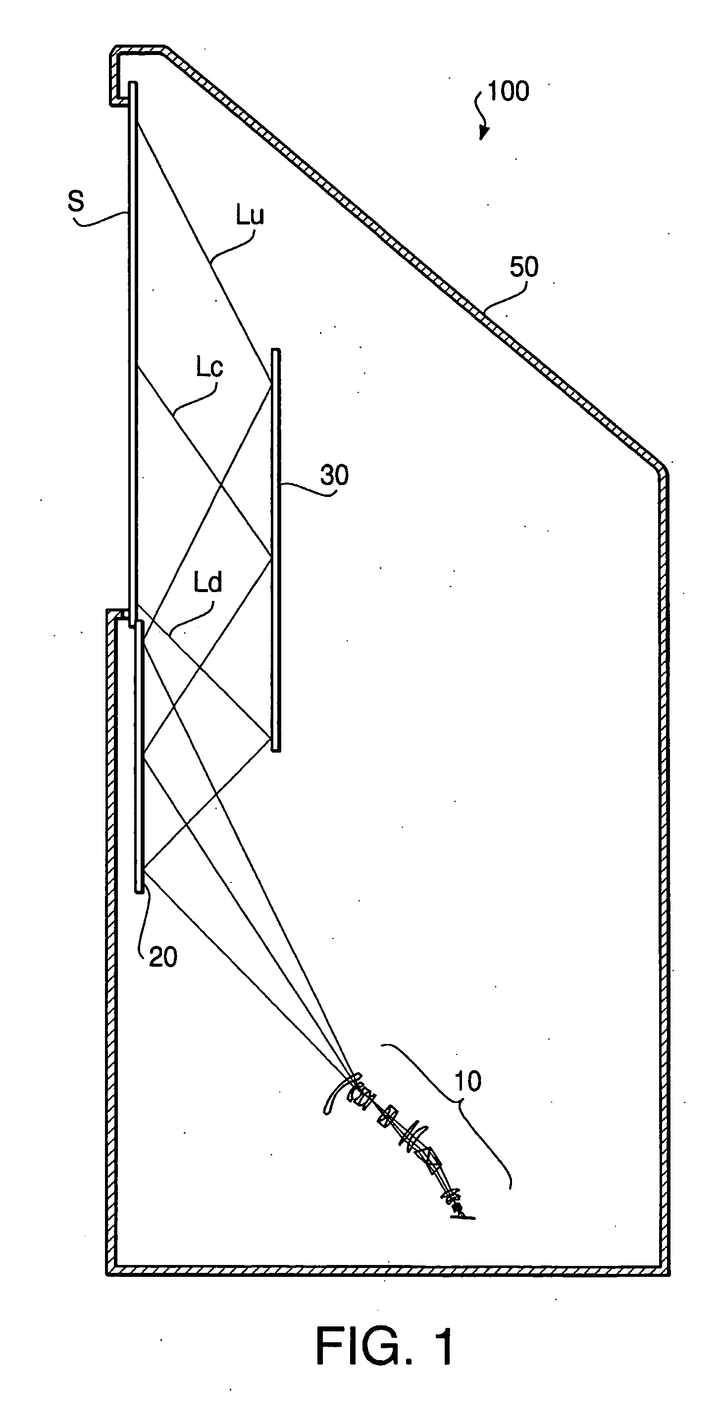
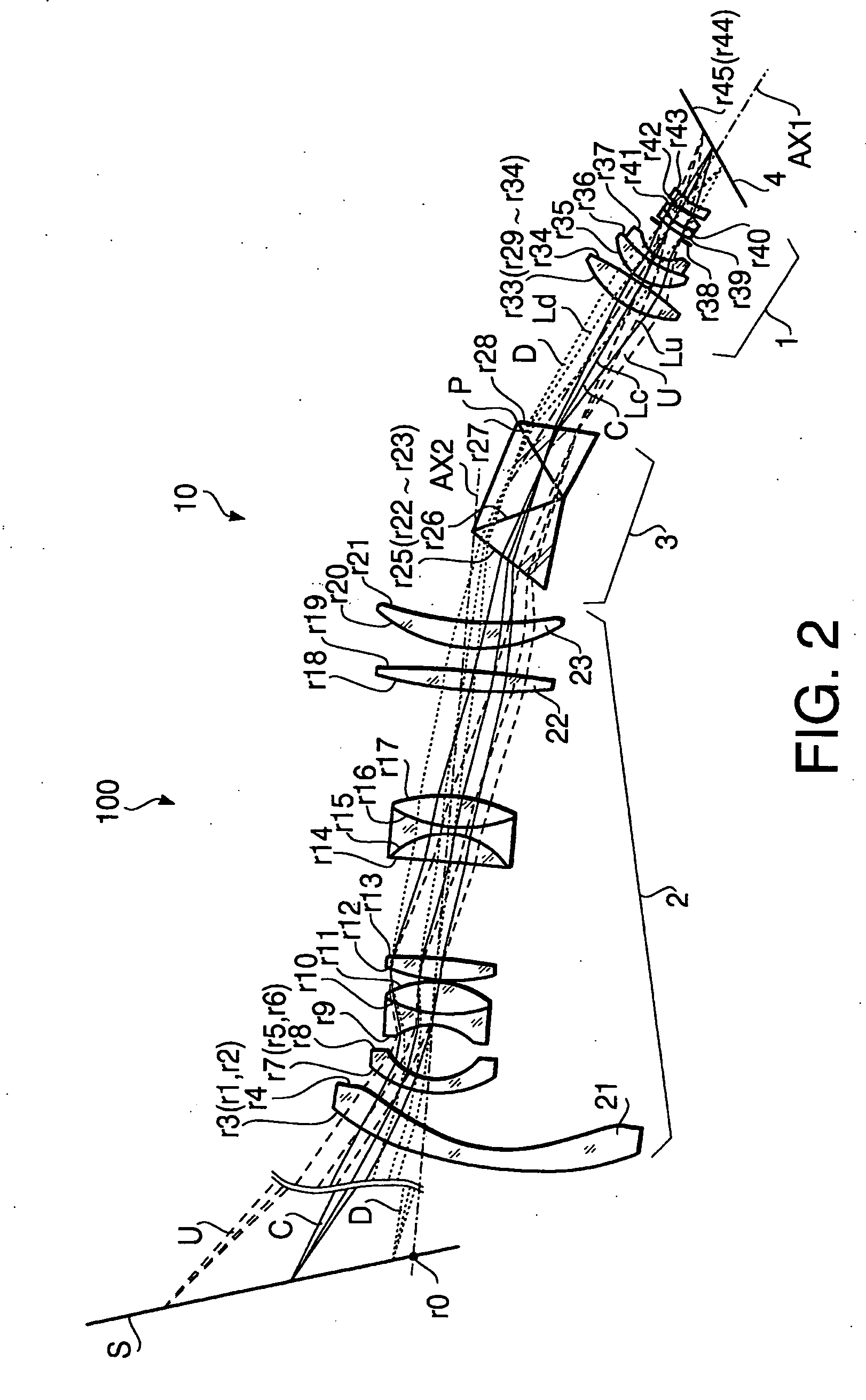
[0070] In the projecting device 100 of the first example, the screen S and the projective optical system 10 are arranged as shown in FIG. 2. The following Table 1 shows specific numerical values of the projecting device 100 of the first example. The “tilt” (deg) of each element in Table 1 means a tilt angle from the first / second imaginary plane P1 / P2 (see FIG. 3) which is orthogonal to the optical axis AX1 / AX2. A positive tilt means a tilt in the counterclockwise direction in FIG. 2. The “shift amount” of each element in Table 1 means a shift amount of the center of the element from the optical axis AX1 / AX2 measured while maintaining the tilt in regard to the optical axis AX1 / AX2. A positive shift amount Y means a shift (of the center of the element) from the optical axis AX1 / AX2 in a direction separating from the first / second reference line L1 / L2 (ditto for the following examples).
TABLE 1CurvatureSurfaceShiftAsphericalAsphericalSurfaceradiusintervalRefractiveAbbeamountTiltCoeffic...
second example
[0078]FIG. 5 is a schematic diagram mainly showing the composition of a projective optical system 10 of a projecting device 100 as the second example, in which optical paths inside the projecting device 100 (between the projective optical system 10 and the screen S) are unfolded for convenience. The following Table 2 shows specific numerical values of the projecting device 100 of the second example.
TABLE 2CurvatureSurfaceShiftAsphericalAsphericalSurfaceradiusintervalRefractiveAbbeamountTiltCoefficientCoefficientNo.(mm)(mm)indexnumber(mm)[deg.](4th order)(6th order)CommentsScreen S0∞0.02nd1∞820.0−34.3Projective2330.05.01.6341.6optical3258.83.8system4∞0.0−12.05132.45.01.49355.2−3.81.1024E−06−6.6455E−11*1645.00.0−3.3781E−07−2.6587E−09*17∞−5.03.88∞28.312.0927.73.61.83128.71014.715.311−15.83.01.76737.81234.38.91.69349.113−23.70.51446.25.71.84623.815−202.327.416−6468.18.31.76846.217−19.51.81.83631.01837.28.31.55867.019−44.630.120151.35.01.82643.221−384.56.72242.27.11.60365.523103.84.0De...
third example
[0086]FIG. 6 is a schematic diagram mainly showing the composition of a projective optical system 10 of a projecting device 100 as the third example, in which optical paths inside the projective device 100 (between the projective optical system 10 and the screen S) are unfolded for convenience. The following Table 3 shows specific numerical values of the projecting device 100 of the third example.
TABLE 3CurvatureSurfaceShiftAsphericalAsphericalSurfaceradiusintervalRefractiveAbbeamountTiltCoefficientCoefficientNo.(mm)(mm)indexnumber(mm)[deg.](4th order)(6th order)CommentsScreen S0∞0.02nd1∞820.0−34.3projective2∞0.0optical365.25.01.49355.2*3system430.20.0*35∞−5.06∞14.5727.73.61.83128.7814.715.39−15.83.01.76737.81034.38.91.69349.111−23.70.51246.25.71.84623.813−202.327.414−6468.18.31.76846.215−19.51.81.83631.01637.28.31.55867.017−44.630.118151.35.01.82643.219−384.56.72042.27.11.60365.521103.84.0Deflecting22∞0.0−5.2optical23∞0.0−14.7system 324∞14.7−19.9*225∞14.01.70930.340.0*226∞14.71.7...
PUM
 Abstract
Description
Claims
Application Information
 - R&D
- Intellectual Property
- Life Sciences
- Materials
- Tech Scout
- Unparalleled Data Quality
- Higher Quality Content
- 60% Fewer Hallucinations
Browse by: Latest US Patents, China's latest patents, Technical Efficacy Thesaurus, Application Domain, Technology Topic, Popular Technical Reports.
© 2025 PatSnap. All rights reserved.Legal|Privacy policy|Modern Slavery Act Transparency Statement|Sitemap|About US| Contact US: help@patsnap.com


