Diffusion plate used in direct-type backlight module and method for making the same

Active Publication Date: 2007-01-18
CHI MEI CORP
View PDF2 Cites 75 Cited by
  • Summary
  • Abstract
  • Description
  • Claims
  • Application Information

AI Technical Summary

Benefits of technology

[0008] One objective of the present invention is to provide a diffusion plate used in a direct-type backlight module. At least one of the surfaces of the diffusion plate has a microstructure constituted by repeated undulation that can refract and diffuse the incident light beams that enter the diffusion plate. Therefore, the paths of the light beams after entering the diffusion plate are changed, which raises the luminance of the backlight module.
[0009] Another objective of the present invention is to provide a method for making a diffusion plate used in a direct-type backlight module. The method utilizes a corolling process to make a diffusion plate with composite structure and form a microstructure on the surface of the diffusion plate. Therefore, the paths of the light beams after entering the diffusion plate are changed, which raises the luminance of the backlight

Problems solved by technology

However, the optical defects easily occur on the optical films due to the environmental affect so that the yield of the backlight module 1 is lowered.
Additionally, the optical films are expensive,

Method used


Image

  • Diffusion plate used in direct-type backlight module and method for making the same
  • Diffusion plate used in direct-type backlight module and method for making the same
  • Diffusion plate used in direct-type backlight module and method for making the same

Examples


first embodiment

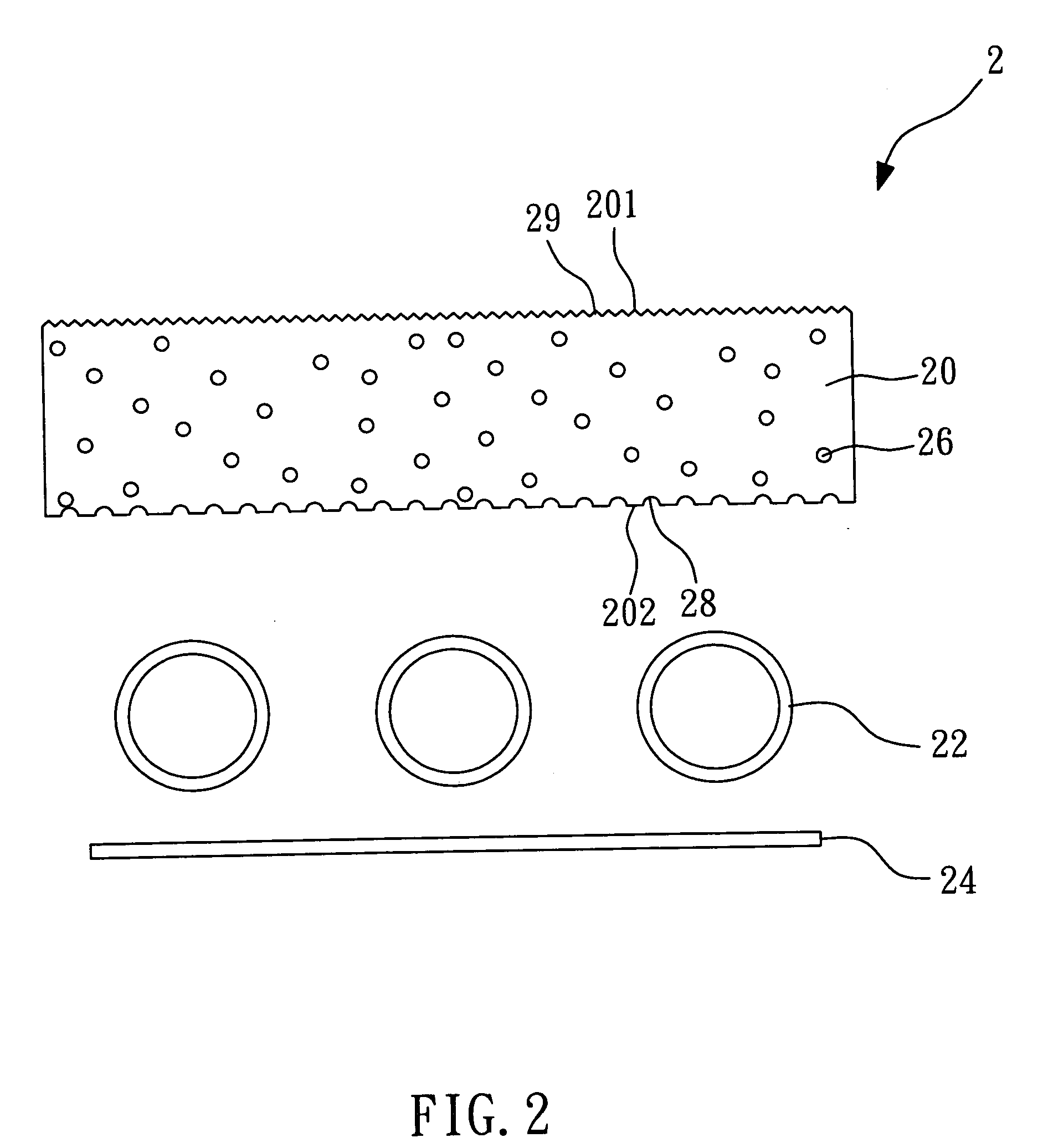
[0018]FIG. 2 shows a schematic view of a direct-type backlight module according to the present invention. The direct-type backlight module 2 is used in a display device and comprises a diffusion plate 20, a plurality of lamps 22, a reflector 24, and a plurality of diffusion particles 26.

[0019] The diffusion plate 20 is a transparent body doped with the diffusion particles 26 therein. The second refractive index n2 of the diffusion particles 26 is different from the first refractive index n1 of the body of the diffusion plate 20. The light beams in the diffusion plate 20 are diffused due to the refraction of the diffusion particles 26 so that the lamp mura between the lamps 22 can be reduced. The diffusion plate 20 has a top surface 201 and a bottom surface 202.

[0020] The bottom surface 202 of the diffusion plate 20 is an illuminated surface for receiving the incident light beams emitted from the lamps 22 directly and the incident light beams reflected by the reflector 24. In the em...

second embodiment

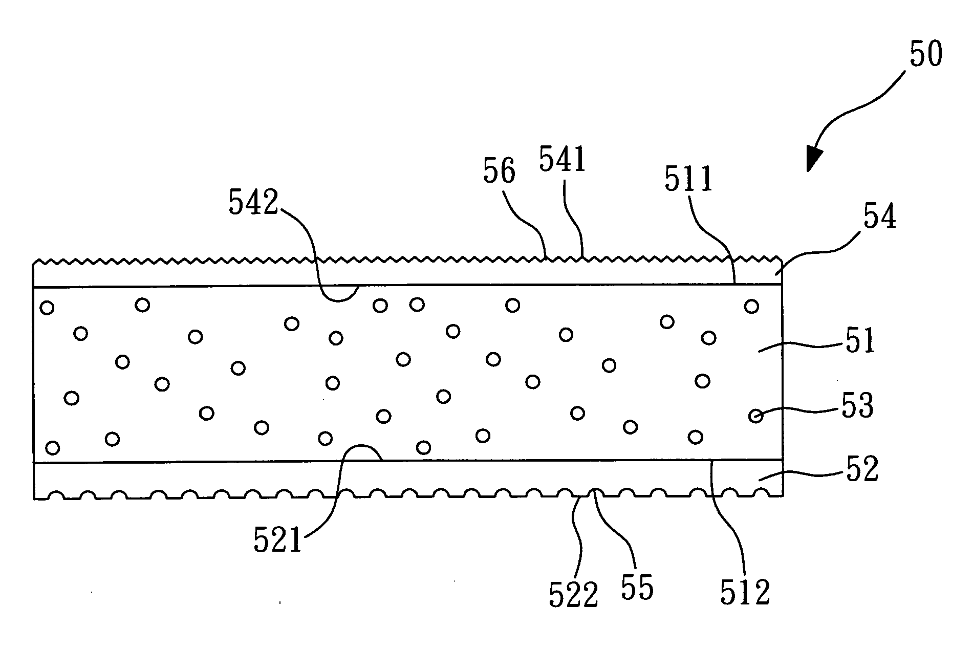
[0022]FIG. 3 shows a schematic view of a diffusion plate according to the present invention. The diffusion plate 30 of the embodiment is used in a direct-type backlight module and comprises a body 31, an upper layer 32 and a plurality of diffusion particles 33. The body 31 has a top surface 311 and a bottom surface 312. The body 31 has a first refractive index n1. The diffusion particles 33 are doped in the body 31 and have a second refractive index n2. The light beams in the body 31 are diffused due to the refraction of the diffusion particles 33. The upper layer 32 is a transparent material and has a top surface 321 and a bottom surface 322. The upper layer 32 has a fourth refractive index n4. In the embodiment, the first refractive index n1 is different from the second refractive index n2, and the first refractive index n1 is larger than the fourth refractive index n4.

[0023] The bottom surface 312 of the body 31 is an illuminated surface for receiving the incident light beams. In...

third embodiment

[0025]FIG. 4 shows a schematic view of a diffusion plate according to the present invention. The diffusion plate 40 of the embodiment comprises a body 41, a lower layer 42 and a plurality of diffusion particles 43. The body 41 has a top surface 411 and a bottom surface 412. The body 41 has a first refractive index n1. The diffusion particles 43 are doped in the body 41 and have a second refractive index n2. The light beams in the body 41 are diffused due to the refraction of the diffusion particles 43. The lower layer 42 is a transparent material and has a top surface 421 and a bottom surface 422. The lower layer 42 has a third refractive index n3. In the embodiment, the first refractive index n1 is different from the second refractive index n2, and the first refractive index n1 is larger than the third refractive index n3.

[0026] The top surface 421 of the lower layer 42 is attached to the bottom surface 412 of the body 41. The bottom surface 422 of the lower layer 42 is an illumina...


PUM


Abstract

The present invention relates to a diffusion plate used in a direct-type backlight module and a method for making the same. At least one of the surfaces of the diffusion plate has a microstructure constituted by repeated undulation that can refract and diffuse the incident light beams that enter the diffusion plate. Therefore, the paths of the light beams after entering the diffusion plate are changed, which raises the luminance of the backlight module.

Description

BACKGROUND OF THE INVENTION [0001] 1. Field of the Invention [0002] The present invention relates to a diffusion plate used in a direct-type backlight module and a method for making the same, particularly to a diffusion plate having a microstructure on the illuminated surface thereof and a method for making the same. [0003] 2. Description of the Related Art [0004]FIG. 1 shows a schematic view of a conventional direct-type backlight module. The direct-type backlight module 1 is used in a liquid crystal display and comprises a diffusion plate 10, a plurality of lamps 12, a reflector 14, a diffusion film 16, a brightness enhancement film (BEF) 18 and a plurality of diffusion particles 19. [0005] The diffusion plate 10 is a transparent body doped with the diffusion particles 19 therein or thereon. The refractive index of the diffusion particles 19 is different from that of the body of the diffusion plate 10. The light beams in the diffusion plate 10 are diffused due to the refraction of...

Claims


Application Information

Patent Timeline
IPC IPC(8): G02B13/20
CPCG02B5/0221G02B5/0231G02B5/0278G02B5/0268G02B5/0242Y10S359/90
Inventor LEE, MAO-SONGSHIH, HSI-HSINTSAI, SHEN-YINCHANG, TIEN-CHIEHKUO, CHIN-LUNGLIN, JUN-HONGCHENG, SHIH-KAI
Owner CHI MEI CORP
Why Eureka
Try Eureka