
Optical pickup device and information processing apparatus incorporating the optical pickup

a technology of optical pickup and information processing apparatus, which is applied in the direction of digital signal error detection/correction, instruments, recording signal processing, etc., can solve the problems of servo failure, increase the power consumption of the actuator,

Active Publication Date: 2007-01-18
PANASONIC CORP
View PDF4 Cites 4 Cited by
  • Summary
  • Abstract
  • Description
  • Claims
  • Application Information

AI Technical Summary

Benefits of technology

[0017] Another objective of the present invention is to ensure that an objective lens is prevented from colliding directly with an optical disk even when focus servo fails due to a strong impact during recording / reproduction, or when vibration occurs while focus servo is not active.
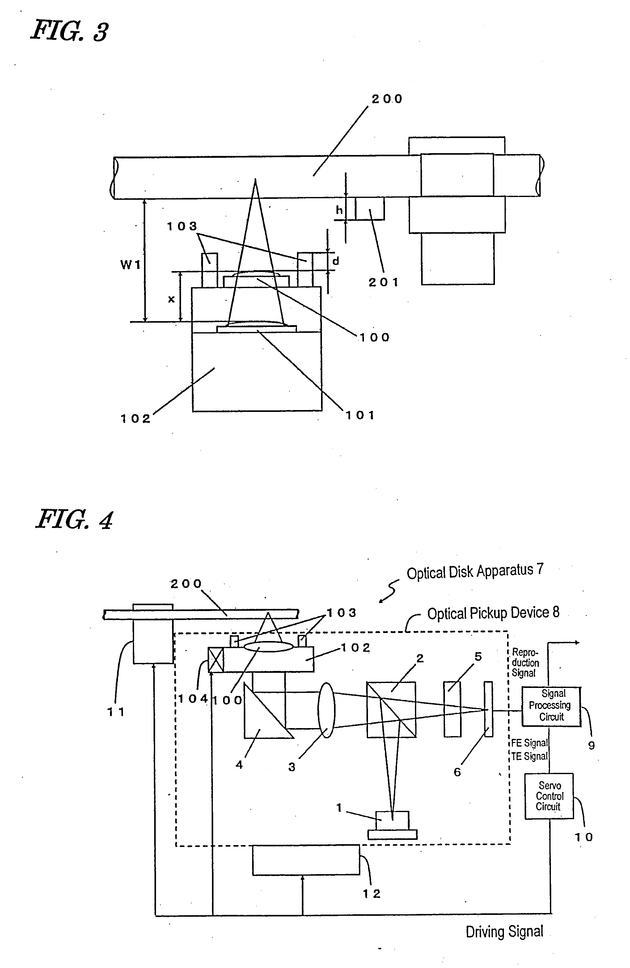
[0027] With an optical pickup device according to the present invention, while a light beam which is converged by a first objective lens having a relatively long working distance is focused on an information recording layer of a corresponding optical disk, a second objective lens having a relatively short working distance and a protective member are at positions which are more distant from the optical disk than the height of a stack rib which is provided at the inner periphery of the optical disk. Therefore, even while performing recording / reproduction for an innermost peripheral portion of the optical disk, the second objective lens having a shorter working distance and the protective member will not come in contact with the stack rib to cause malfunctioning such as servo failure.

Problems solved by technology

This not only requires the actuator to be capable of moving over an enlarged range, but also increases the power consumption of the actuator, corresponding to the offset.
However, when performing recording / reproduction at an inner peripheral portion of the optical disk by using the objective lens having a longer working distance, the objective lens having a shorter working distance and the protective member may come in contact with a protrusion (stack rib) which is formed at the inner peripheral portion of the optical disk, thus causing malfunctioning such as servo failure.

Method used


Image

  • Optical pickup device and information processing apparatus incorporating the optical pickup
  • Optical pickup device and information processing apparatus incorporating the optical pickup
  • Optical pickup device and information processing apparatus incorporating the optical pickup

Examples


Embodiment Construction

[0040] Hereinafter, an embodiment of an optical pickup device according to the present invention will be described with reference to the drawings.

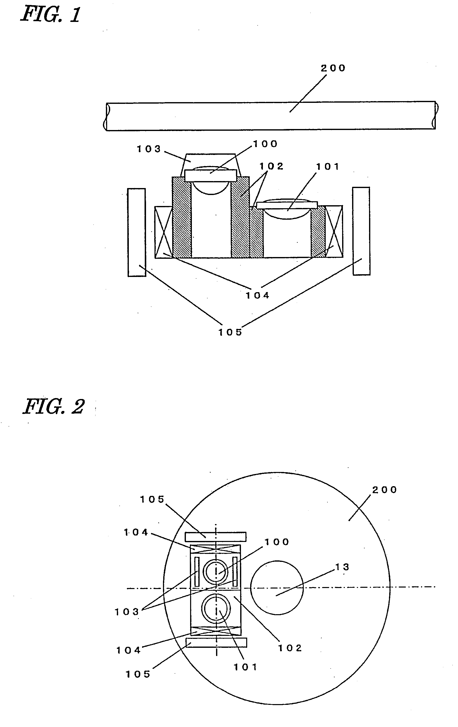
[0041] First, FIG. 1 is referred to FIG. 1 shows a main portion of an optical pickup device according to the present embodiment.

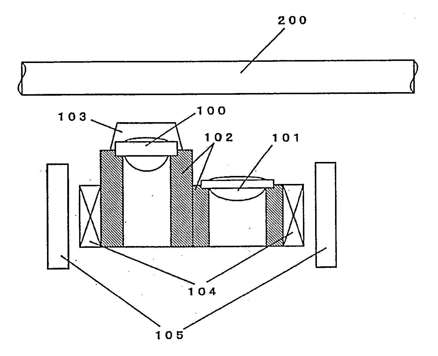
[0042] As shown in FIG. 1, an objective lens 100 and an objective lens 101 are held on a lens holder 102, so as to be in predetermined positions relative to each other. On a surface of the lens holder 102 facing an optical disk 200, a protective member 103 is provided so as to surround the objective lens 100. Coils 104 are attached to the lens holder 102, and magnets 105 are provided in positions respectively opposing the coils 104. Each coil 104 and its corresponding magnet 105 together define a magnetic circuit, which allows the position of the lens holder 102 to be controlled by adjusting the amount of current flowing through the coil 104.

[0043] The objective lenses 100 and 101 converge light beams of differ...


PUM

PropertyMeasurementUnit
wavelengthaaaaaaaaaa

Abstract

A highly reliable optical pickup which is not likely to collide with an optical disk is provided. Relative positions of two objective lenses 100 and 101 (along a focus direction) on a lens holder 102 are determined so that, while the objective lens 101 having a longer working distance is focused on an optical disk 200, the objective lens 100 having a shorter working distance and a protective member 103 are at positions which are more distant from the optical disk 200 than a height h of a protrusion which is present in an inner peripheral region of the optical disk optical disk 200.

Description

BACKGROUND OF THE INVENTION [0001] 1. Field of the Invention [0002] The present invention relates to: an optical pickup device for performing recording / reproduction for a plurality of types of optical disks, such as digital versatile discs (hereinafter referred to as “DVDs”) and Blu-ray discs (hereinafter referred to as “BDs”); and an information processing apparatus incorporating the optical pickup device. [0003] 2. Description of the Related Art [0004] A DVD is known as an optical disk that allows for recording with a recording density which is about six times the recording density of a CD, such that large-capacity digital data (e.g., movies or music) can be written thereto. In the recent years, the increasing amounts of information to be recorded have called for optical disks with greater capacities. [0005] In order to increase the capacity of an optical disk, it is necessary to increase the recording density of information. This is generally realized by reducing the spot diamete...

Claims


Application Information

Patent Timeline
Patent Type & Authority Applications(United States)
IPC IPC(8): G11B7/00
CPCG11B7/0935G11B2007/0006G11B7/1374G11B7/1201G11B7/121
Inventor BOKU, KOURETSUWAKABAYASHI, KANJIKOMMA, YOSHIAKIHAYASHI, HIDEKI
Owner PANASONIC CORP
Learn More