Optical system of optical pick-up

Active Publication Date: 2007-04-24
KONICA MINOLTA INC
View PDF12 Cites 1 Cited by
  • Summary
  • Abstract
  • Description
  • Claims
  • Application Information

AI Technical Summary

Benefits of technology

[0010]The present invention is advantageous in that it provides an optical system of an optical pick-up which is capable of suffi

Problems solved by technology

However, when the optical pick-up disclosed in each of the publications is used to record data to and/or reproduce data from the DVD, the effect of the amounts of aberrations caused when the objective lens shifts due to the focusing operation or the tracking operation increases to a degree that the recording or reproducing operation is affected.
In such a CD/DVD compatible optical pick-up, the same problem may occur when the con

Method used


Image

  • Optical system of optical pick-up
  • Optical system of optical pick-up
  • Optical system of optical pick-up

Examples


first embodiment

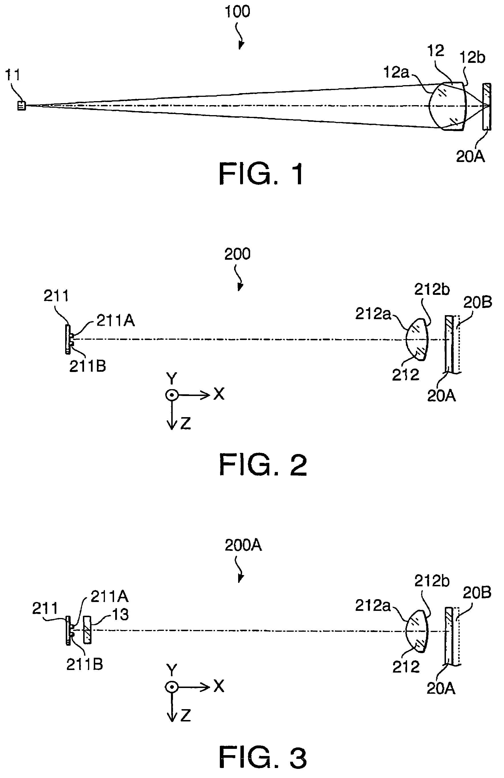
[0073]FIG. 1 shows a configuration of an optical system 100 according to a first embodiment of the invention. The optical system 100 is used in an optical pick-up of an optical disc apparatus which records data to and / or reproduces data from an optical disc 20A having relatively high recording density and having relatively thin cover layer. The optical disc 20A is, for example, a DVD.

[0074]The optical system 100 includes a light source 11 and an objective lens 12. The optical disc 20A shown in FIG. 1 is placed on a turntable (not shown) provided in the optical disc apparatus.

[0075]As shown in FIG. 1, the optical system 100 does not have a coupling lens. That is, a laser beam emitted by the light source 11 is converged onto a data recording layer of the optical disc 20A only by the objective lens 12.

[0076]The light source 11 emits the laser beam having a relatively short wavelength suitable for the optical disc 20A. The laser beam emitted by the light source 11 is converged by the ob...

second embodiment

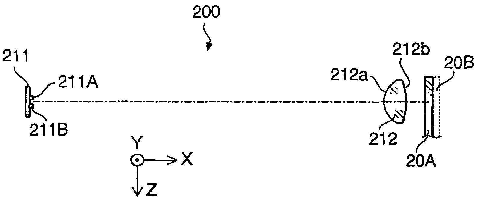
[0087]Hereafter, a second embodiment of the invention will be described. FIG. 2 shows a configuration of an optical system 200 according to the second embodiment of the invention. In FIG. 2 (and in FIG. 3), to elements which are similar to those in FIG. 1, the same reference numbers are assigned, and the detailed description thereof will not be repeated.

[0088]The optical system 200 is used in an optical pick-up of an optical disc apparatus which records data to and / or reproduces data from a plurality of types of optical discs having different thicknesses of cover layers. In this embodiment, the optical system 200 is used to record data to and / or reproduce data from the optical disc 20A and an optical disc 20B. The optical disc 20B has the thickness of cover layer larger than that of the optical disc 20A and has a recording density lower than that of the optical disc 20A. The optical disc 20B is, for example, a CD. One of the optical discs 20A and 20B is placed on a turntable (not sh...

first example

[0109]An optical system according to a first example has a configuration described in the first embodiment with reference to FIG. 1. Therefore, the first example will be explained with reference to FIG. 1. Tables 1 and 2 show a numerical configuration of the optical system 100 of the first example.

[0110]

TABLE 1Optical Disc 20AM−1 / 10.40DESIGN655WAVELENGTHNA0.60L38.90

[0111]

TABLE 2SurfaceNumberrdlnv#035.00#12.1503.201.54455.7#2−3.8151.45#30.601.58529.9#4—

[0112]In Table 1, M represents the magnification, the design wavelength is a wavelength suitable for the recordation / reproduction of the optical disc being used, NA is a numerical aperture on the optical disc side, and L represents the O / I distance (mm). In this example, the optical disc 20A (e.g., DVD) is used. These symbols are also applied to similar tables in concrete examples indicated below.

[0113]In Table 2, “surface number” represents a surface number of each surface of optical components in the optical system 100. A surface #0 ...


PUM


Abstract

An optical system of an optical pick-up, which is provided with a light source that emits a light beam, and an objective lens that converges the light beam emitted by the light source onto a data recording layer of an optical disc. The optical system satisfies a condition: 0.75<d·(M−1)/(M·L)<1.0, where d (mm) represents a thickness of the objective lens, M represents magnification of the optical system, and L (mm) represents an O/I distance which is defined as a distance between an object and an image. A beam spot suitable for the optical disc is formed by the objective lens on the data recording layer of the objective lens without using a coupling lens.

Description

BACKGROUND OF THE INVENTION[0001]The present invention relates to an optical system for an optical pick-up which is capable of recording data to and / or reproducing data from one or more kinds of optical discs having different thicknesses of cover layers.[0002]There are various types of optical discs such as a CD (compact disc) and a DVD (digital versatile disc). The DVD has the cover layer thinner than that of the CD, and has a data recording density larger than that of the CD. For supporting both of the CD and DVD, the optical pick-up is required to have a configuration which enables to correct a spherical aberration which changes depending on the thickness of cover layer of an optical disc being used and to change NA (numerical aperture) of a light beam so as to attain a diameter of a beam spot suitable for the data recording density of the optical disc being used.[0003]In general, the optical pick-up has a light source for emitting the light beam, a coupling lens, and an objectiv...

Claims


Application Information

Patent Timeline
IPC IPC(8): G11B7/00G11B7/135
CPCG11B7/1374G11B2007/0006
Inventor TAKEUCHI, SHUICHI
Owner KONICA MINOLTA INC
Why Eureka
Try Eureka