Prime mover and working method

A technology of prime mover and work, applied in the field of prime mover, can solve the problems of large kinetic energy or electric energy consumption, inability to produce economic benefits, long refrigerant flow path, etc., and achieve the effect of large output force, low cost and large speed ratio

Pending Publication Date: 2021-03-16
钟学斌
View PDF8 Cites 0 Cited by
  • Summary
  • Abstract
  • Description
  • Claims
  • Application Information

AI Technical Summary

Problems solved by technology

In this invention, it is necessary to depressurize through the expansion mechanism 15 and evaporate through the first evaporator 16. After the evaporation occurs and expands to perform work on the rotary vane power machine 17, it is then compressed back to the first condenser 13 through the generating state working fluid compressor 12. Circulation, in the circulation path of doing work, the evaporation and liquefaction of the refrigerant requires the expansion mechanism and the generating gas working medium compressor 12 respectively, which increases the cost and consumes a large amount of kinetic energy or electric energy, resulting in a waste of energy and cannot generate economic benefits. At the same time, with the design of this kind of circulation pipeline, the refrigerant flow path is long, and part of the energy will be lost on the way, which will also cause energy loss

Method used


Image

  • Prime mover and working method
  • Prime mover and working method
  • Prime mover and working method

Examples


Embodiment Construction

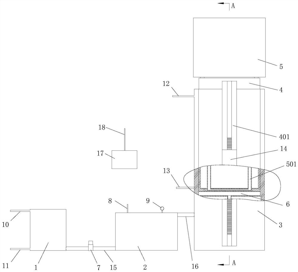
[0053] The following detailed description will set forth the general principles of the invention, examples of which are additionally illustrated in the accompanying drawings. In the drawings, like reference numbers indicate identical or functionally similar elements. As used herein, the term energy fluid may include any liquid.

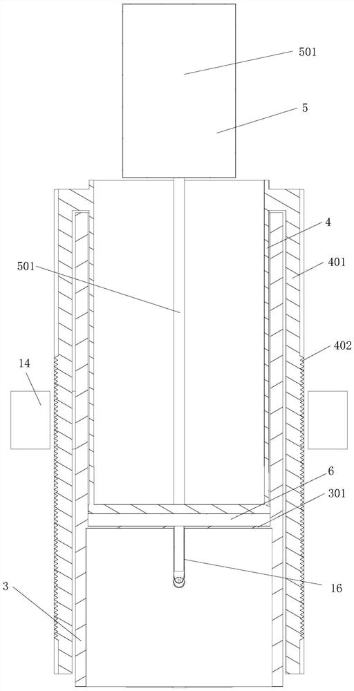
[0054] Such as Figure 1-2 As shown, the present invention includes an evaporator 2, a body 3 and an energy body 4, the energy body 4 is slidably arranged in the body 3, and a closed mold cavity 6 is formed between the bottom of the energy body 4 and the inner wall of the body 3, and the evaporator 2 and The bottom of the cavity 6 is connected, and the evaporator 2 continues to absorb heat and evaporate the liquid working medium to push the energy body 4 to move up to do work until the upper limit stroke. When the ambient temperature meets the liquefaction temperature, the energy body 4 moves down due to its own weight and compresses the gaseous work...


PUM


Abstract

The invention belongs to a prime mover, and particularly relates to a prime mover and a working method. The prime mover comprises an evaporator, a machine body and an energy body, wherein the energy body is arranged in the machine body in a sliding mode; a closed cavity is formed between the bottom of the energy body and the inner wall of the machine body; the evaporator communicates with the cavity and continuously absorbs heat to evaporate a liquid working medium, and the volume of the working medium expands due to evaporation so as to push the energy body to move upwards to do work until the upper limit stroke; and when the ambient temperature is lower than the evaporation temperature, the energy body moves downwards to compress the gaseous working medium due to self weight to completethe liquefaction. According to the prime mover and the working method, the evaporator evaporates the liquid working medium, the volume expansion pushes the energy body to move upwards to do work, andthe mechanical energy is output; when the ambient temperature meets the set value of the liquefaction stroke, the gaseous working medium is compressed by the self weight of the energy body to carry out the liquefaction stroke; the whole working stroke and liquefaction stroke do not need other auxiliary equipment, so that unnecessary energy loss is avoided; and the whole structure is simple, the cost is low, the performance is stable, the efficiency is high, and the positive economic value is realized.

Description

technical field [0001] The invention belongs to a prime mover, and in particular relates to a prime mover and a work method. Background technique [0002] Prime mover refers to all machinery that uses energy to generate motive force. It is the main source of power required in the fields of modern production and life. [0003] At present, in the equipment that converts air heat energy into mechanical energy, the working fluid with low evaporation temperature is generally used to absorb heat and expand to do work. However, this kind of evaporation from liquid to gas requires special mechanical equipment to complete, and the gaseous working fluid returns to liquid. It also requires Use other equipment to compress the gaseous working medium or increase the exhaust pressure to complete it. This method will reduce the working pressure difference and reduce the work. For example, the gaseous working medium is compressed into a liquid state by a compression machine. The above two s...

Claims


Application Information

Patent Timeline
Patent Type & Authority Applications(China)
IPC IPC(8): F01K11/00F01K13/02
CPCF01K11/00F01K13/02Y02E10/46Y02E10/20F01K13/00
Inventor 钟学斌
Owner 钟学斌
Why Eureka
Try Eureka