Packet Detection System, Packet Detection Device, and Method for Receiving Packets

a packet detection and packet technology, applied in the field of packet detection systems, can solve the problems of interference in transmitted data, packet detection devices b>20/b> not operable with ultra wideband wireless communication systems, and hopping signals generated by frequency hopping technology are merely nois

Inactive Publication Date: 2007-01-18
FARADAY TECH CORP
View PDF5 Cites 44 Cited by
  • Summary
  • Abstract
  • Description
  • Claims
  • Application Information

AI Technical Summary

Problems solved by technology

Typically, Inter Symbol Interference (ISI) is largely caused by a limited bandwidth in high-speed data transmission, producing interference in the transmitted data.
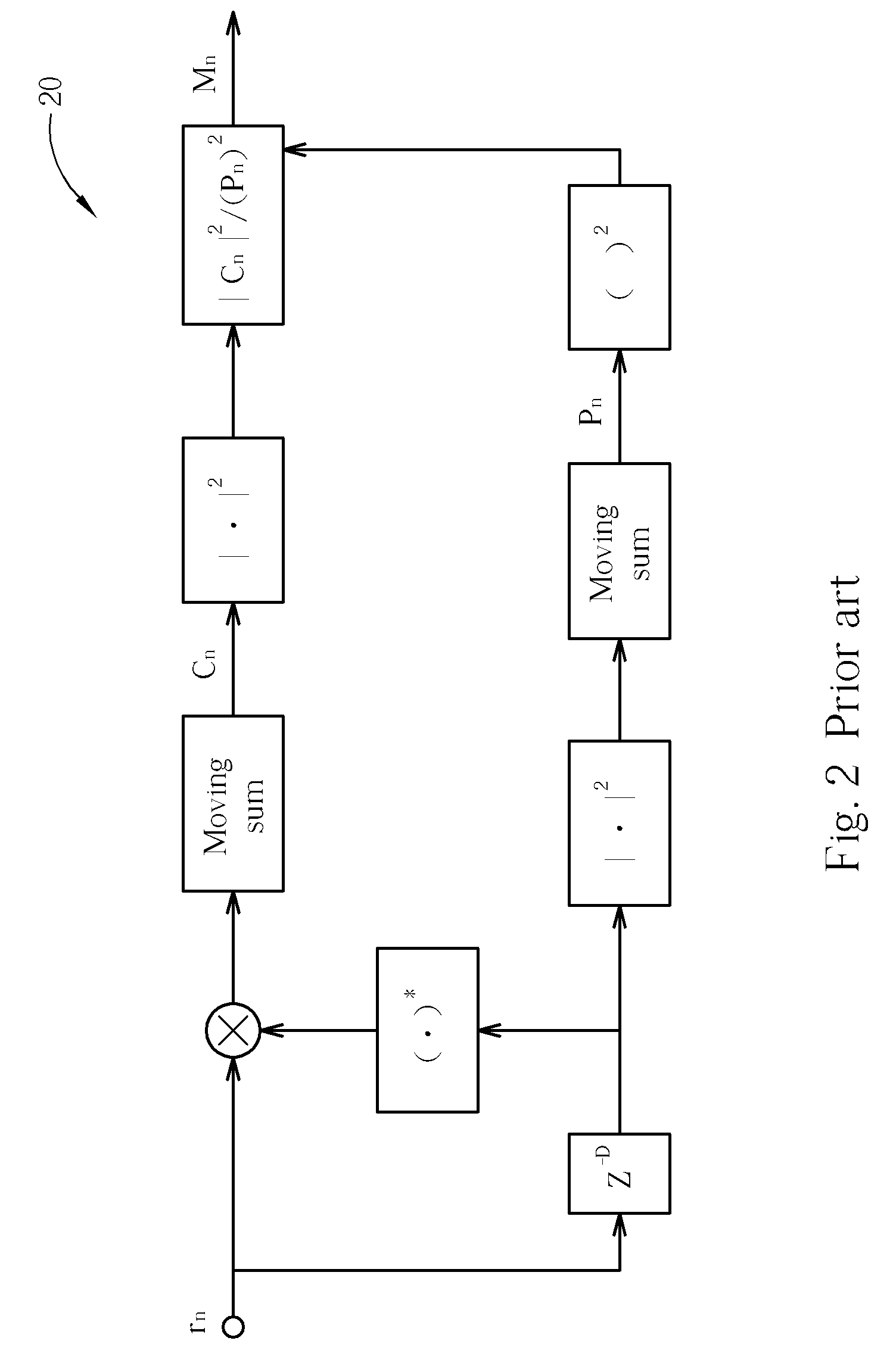
However, the packet detection device 20 is not operable with the ultra wideband wireless communication system utilizing the MB-OFDM technology for the reasons listed below:
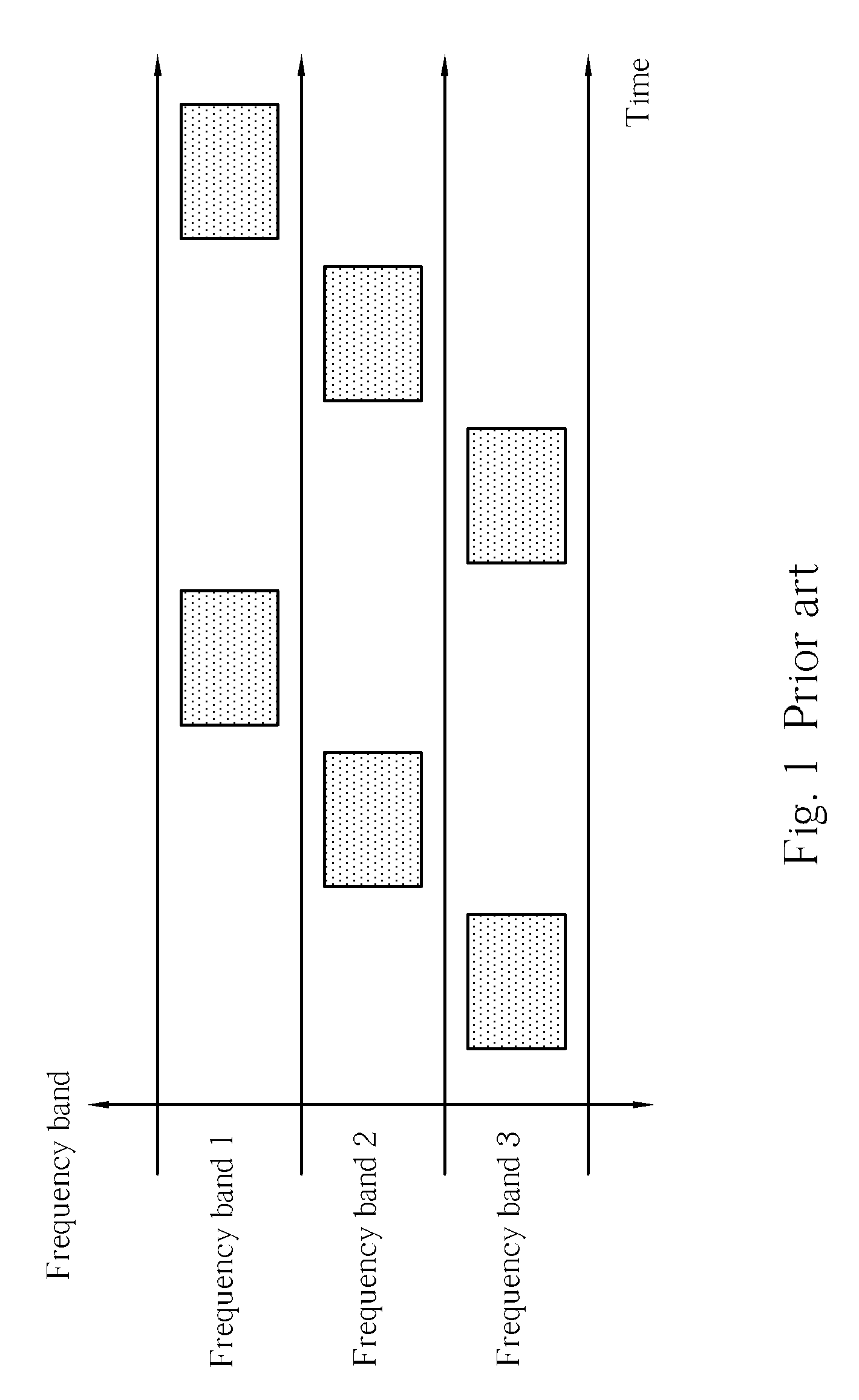
For other receiving ends, the hopping signals generated by the frequency hopping technology are merely noise.
However, the traditional packet detection device 20 cannot detect the corresponding packet due to different time frequency codes.
Therefore the traditional packet detection device 20 is not applicable on the UWB wireless communication system utilizing MB-OFDM technology.
Timing detection issue: when the transmission end of the MF-OFDM system utilizes a zero-padding prefix, the receiving end cannot obtain accurate timing information.
However, when the zero-padding prefix is employed in the MB-OFDM system (as shown in FIG. 4), the conventional packet detector cannot determine the precise FFT window position thus the processing of the signal afterwards will be affected.
Therefore in order to realize high-speed transmission through a multi-band orthogonal frequency division multiplexing system, design of the receiving end of the packet detection device is a very relevant issue.

Method used


Image

  • Packet Detection System, Packet Detection Device, and Method for Receiving Packets
  • Packet Detection System, Packet Detection Device, and Method for Receiving Packets
  • Packet Detection System, Packet Detection Device, and Method for Receiving Packets

Examples


Embodiment Construction

[0029] This section details an ultra wideband system that utilizes a multi-band orthogonal frequency division multiplexing technology. A packet is outputted from the transmission end, usually comprises a preamble block for defining information like timing and band of the packet. The preamble block corresponds to a preamble sequence of a predetermined time frequency code, and incorporates a plurality of coefficients. Please refer to FIG. 5. FIG. 5 illustrates a diagram of a Physical Layer Convergence Procedure (PLCP) packet 500. The physical layer convergence procedure packet 500 comprises a preamble block 502, a header 504, an optional extension 506, a payload 508, a check 510, a tail 512 and a padding 514. Each block of the physical layer convergence procedure packet 500 is well known to those skilled in the art and therefore it does not need to be further explained. The receiving end through the preamble block can perform calculations like synchronization, recovery carrier offset,...


PUM


Abstract

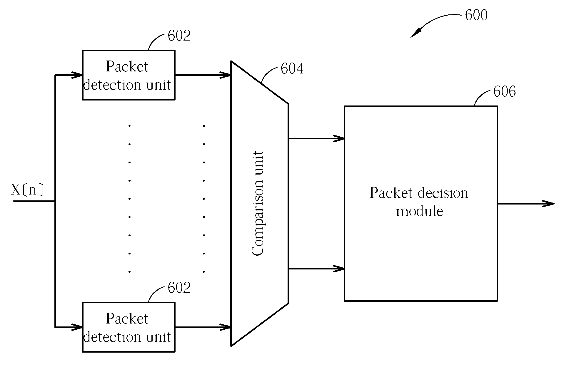
A packet detector for a multi-band orthogonal frequency division multiplexing system includes a plurality of packet detection units each corresponding to a time frequency code for detecting packets according to a spreading sequence of the time frequency code, a comparison unit for comparing correlation values provided by division units of the plurality of packet detection units, and a packet decision module for determining a time frequency code and size of a fast Fourier transform sampling window according to output signals of the comparison unit, allowing a frequency band to be selected and synchronization to be executed.

Description

BACKGROUND OF THE INVENTION [0001] 1. Field of the Invention [0002] The present invention relates to a packet detection system utilized in a multi-band orthogonal frequency division multiplexing system, and more particularly, to a packet detection unit of a packet detection system set to correspond to different time frequency codes. [0003] 2. Description of the Prior Art [0004] In recent years, wireless communication technology and devices have taken a big leap with advances in research and development. More specifically in the field of wireless personal area network (WPAN), the WPAN technique allows users to establish personal wireless transmitting spaces with a longest diameter of 10 meters. Nowadays, the two major WPAN techniques are respectively “Bluetooth” and infrared transmission. “Bluetooth” utilizes EM waves, which are hardly blocked by any obstacle, to transmit data while the infrared transmission can achieve high-speed transmission within a certain distance such as one me...

Claims


Application Information

Patent Timeline
Patent Type & Authority Applications(United States)
IPC IPC(8): H04L12/56
CPCH04L5/023H04L27/2656H04L27/2675H04W56/00H04W24/00
Inventor LAI, JYH-TING
Owner FARADAY TECH CORP
Why Eureka
Try Eureka