
Image processing apparatus and control method therefor

Inactive Publication Date: 2007-01-18
CANON KK
View PDF7 Cites 38 Cited by
  • Summary
  • Abstract
  • Description
  • Claims
  • Application Information

AI Technical Summary

Benefits of technology

[0013] The present invention has been made to solve such problems in the conventional techniques. More specifically, it is the first object of the present invention to improve user's convenience and suppress the creation of unnecessary folders in an image processing apparatus which can store a pickuped image file in a new folder.
[0014] It is the second object of the present invention to allow a user to know that a new folder is to be created at the time of a next shooting in an image processing apparatus which can store a pickuped image file in a new folder.
[0015] It is the third object of the present invention to achieve automatic classification of pickuped image files so as to more satisfy the user's intention in an image processing apparatus which can facilitate classification of pickuped image files by recording them by creating a new folder.
[0018] With this arrangement, according to the present invention, in an image processing apparatus which can store a pickuped image file in a new folder, the user's convenience can be improved, and the creation of unnecessary folders can be suppressed.
[0021] In addition, with this arrangement, according to the present invention, in an image processing apparatus which can store a pickuped image file in a new folder, a user can know that a new folder is to be created at the time of a next shooting.
[0024] With this arrangement, according to the present invention, automatic classification of pickuped image files can be achieved so as to more satisfy the user's intention in an image processing apparatus which can facilitate classification of pickuped image files by recording them by creating a new folder.

Problems solved by technology

In addition, if a new folder is created and set as a recording destination and the recording destination is changed before an actual shooting, an empty, unnecessary folder is left.
Such an empty folder becomes a search target when a search is made for an image in the recording medium to, for example, play back the image, and hence becomes a cause for an increase in search processing time.
In addition, this folder becomes a hindrance when the user searches for a desired image, and hence also becomes a cause for deterioration in operability.
Furthermore, since the new folder designated as a recording destination does not exist in the newly loaded recording medium, a pickuped image file cannot be recorded in the desired folder.
Although these conventional techniques can display the information of created folders and directories, they cannot notify a user of a state wherein a new folder is to be created in conjunction with shooting operation.
For this reason, even if a camera automatically changes the save destination for a pickuped image to a new folder or new directory, the user cannot know it, resulting in difficulty in performing image search processing or the like.
In addition, the above conventional techniques are not designed to display the state of a camera.
Therefore, the user cannot know the timing at which the camera automatically creates a new folder or new directory.
For this reason, it is difficult to change settings as needed and construct a desired folder structure or directory structure.

Method used


Image

  • Image processing apparatus and control method therefor
  • Image processing apparatus and control method therefor
  • Image processing apparatus and control method therefor

Examples


first embodiment

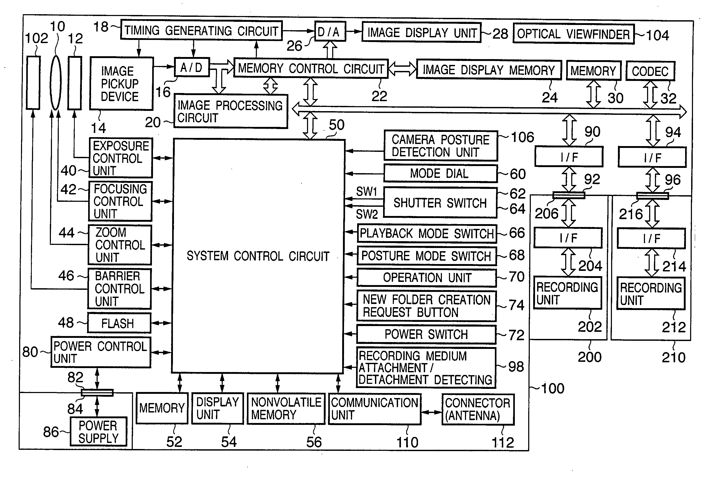
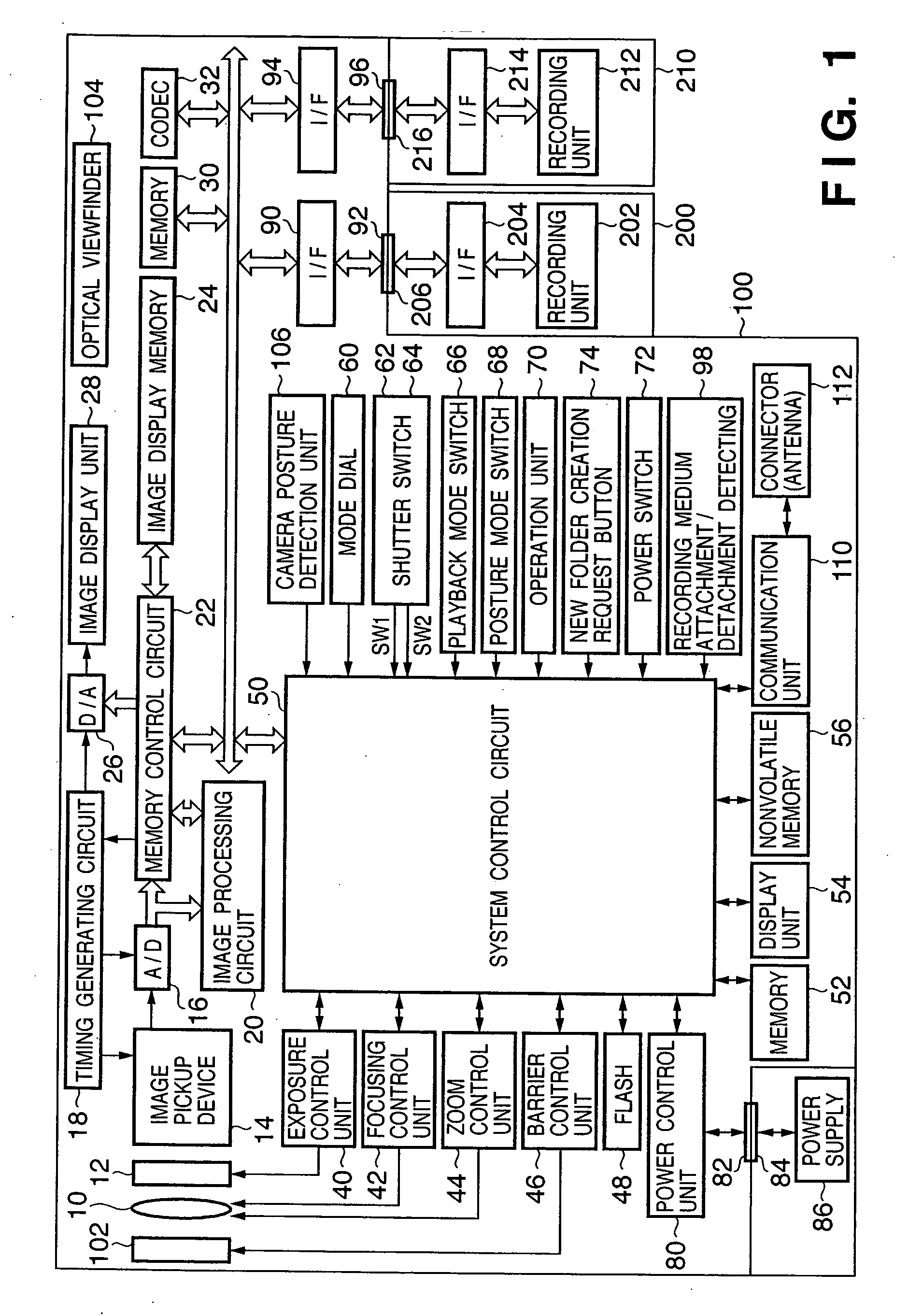
[0052]FIG. 1 is a block diagram showing an example of the arrangement of a digital camera as an example of an image processing apparatus according to an embodiment of the present invention.

[0053] Reference numeral 10 denotes a photographing lens; 12, a shutter having a stop function; 14, an image pickup device such as a CCD or CMOS sensor which converts an optical image into an electrical signal; and 16, an A / D converter which converts an analog signal output from the image pickup device 14 into a digital signal.

[0054] A timing generating circuit 18 supplies clock signals and control signals to the image pickup device 14, the A / D converter 16, and a D / A converter 26, and is controlled by a memory control circuit 22 and a system control circuit 50.

[0055] An image processing circuit 20 performs predetermined pixel interpolation processing and color conversion processing for data from the A / D converter 16 or data from the memory control circuit 22.

[0056] The image processing circui...

second embodiment

[0238] The operation of a digital camera as an example of an image processing apparatus according to the second embodiment of the present invention will be described with reference to FIGS. 3, 5 to 13, 15, 16, 17, and 23.

[0239] Assuming that the digital camera of this embodiment also has the functional arrangement shown in FIG. 1 like the digital camera 100 described in the first embodiment, this digital camera will be described below as a digital camera 100.

[0240] The overall operation of the digital camera 100 will be described first with reference to the flowcharts of FIGS. 23 and 3.

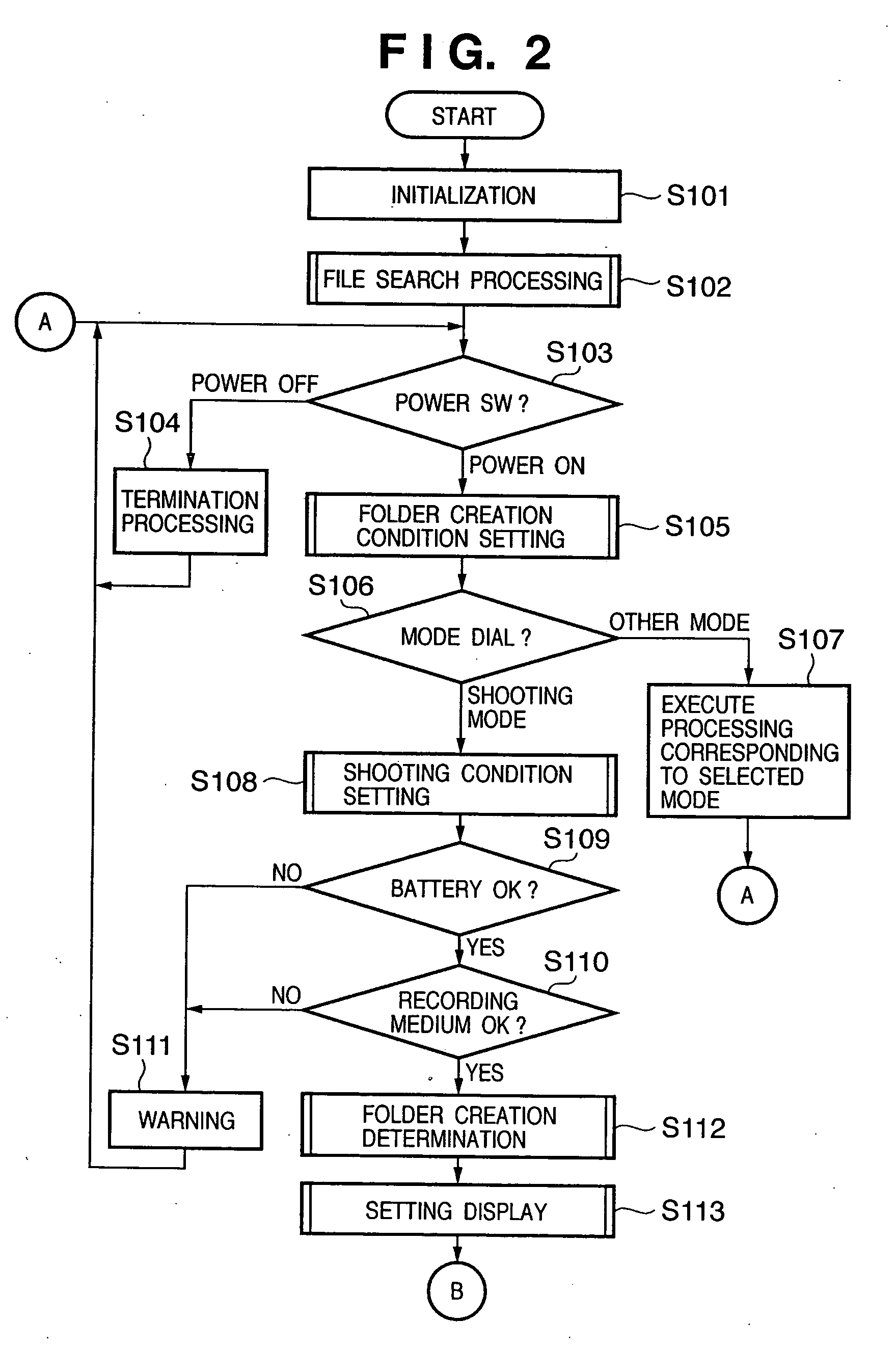
[0241] When the power supply is turned on upon battery change or the like, a system control circuit 50 initializes flags, control variables, and the like (S2301). After the immediately preceding mode name stored in the internal memory or a memory 52 in the system control circuit 50 is set to “activation” (S2302), file search processing in the recording medium is performed (S2303).

[0242] The detail...

third embodiment

[0265] The operation of a digital camera as an example of an image processing apparatus according to the third embodiment of the present invention will be described with reference to FIGS. 2, 3, 5 to 13, 15, 18, and 19.

[0266] Assuming that the digital camera of this embodiment also has the functional arrangement shown in FIG. 1 like the digital camera 100 described in the first embodiment, this digital camera will be described below as a digital camera 100.

[0267] The operation of the digital camera 100 according to the third embodiment is the same as that of the first embodiment except for the folder creation determination processing in step S112 in FIG. 2 and the setting display processing in step S113, and hence only processing characteristic to this embodiment will be described below.

[0268] This embodiment is characterized in that when a folder creation flag is set in the folder creation determination processing executed in step S112 in FIG. 2, more specifically in step S907 i...


PUM


Abstract

In an image processing apparatus which can store a pickuped image file in a new folder, the user's convenience is improved, and the creation of unnecessary folders is suppressed. If a preset condition for the creation of a new folder is satisfied, a new folder is created when a next shooting instruction is issued (S125). Creating a new folder when a shooting is actually performed prevents the creation of an empty folder. In addition, since a folder creation condition can be set in advance, there is no need to execute a sequence of creating a folder for every shooting.

Description

BACKGROUND OF THE INVENTION [0001] 1. Field of the Invention [0002] The present invention relates to an image processing apparatus which pickups and records still and moving images and a control method therefor. [0003] 2. Description of the Related Art [0004] Conventionally, image processing apparatuses, which pickups still and moving images by using an image pickup device such as a CCD sensor or CMOS sensor as represented by digital cameras or digital video cameras have been widely used. In such an image processing apparatus, pickuped images are recorded as digital data files (pickuped image files). [0005] In general, pickuped image files are recorded using a file system (folder structure) using folders (directories). There has been proposed a technique of classifying pickuped image files by using folders at the time of recording operation so as to facilitate search and the like afterwards. Japanese Patent Laid-Open No. 2003-333470 discloses a technique of allowing a user to select...

Claims


Application Information

Patent Timeline
IPC IPC(8): H04N5/91
CPCG11B27/329H04N5/772H04N9/8047H04N5/907H04N9/7921H04N5/781H04N5/76H04N23/00
Inventor NAKASE, YUICHIYOSHIDA, NOBUKAZU
Owner CANON KK
Learn More