Ultrasonic probe, ultrasonographic device, and ultrasonographic method

a technology of ultrasonography and ultrasonography, which is applied in the field of ultrasonography, can solve the problems of increasing the distance between the plurality of transducers, improving the resolution, and reducing the ease of use, so as to improve improve the ease of use. , the effect of improving the resolution of ultrasound images

Inactive Publication Date: 2007-01-18
HITACHI MEDICAL CORP
View PDF7 Cites 22 Cited by
  • Summary
  • Abstract
  • Description
  • Claims
  • Application Information

AI Technical Summary

Benefits of technology

[0010] That is to say, an oscillation element having an electromechanical coupling coefficient changing in accordance with the strength of a direct-current bias can be made small compared with a piezoelectric element. Accordingly, an transducer can be formed with making intervals between the oscillation elements relatively small, and this is equivalent to subdividing the transducer, which makes it possible to improve the resolution of ultrasound images.
[0011] In particular, by making the strength of the direct-current bias applied on each oscillation element different individually, the strength of an ultrasonic wave emitted from each oscillation element differs in accordance with the strength of the direct-current bias. Accordingly, by controlling the strength of the direct-current bias applied on each oscillation element, it b

Problems solved by technology

Accordingly, the mutual distances among the plurality of transducers become large, and a certain limitation arises in the improvement of the resolution (resolving power) of an ultrasound image.
However, according to the method of disposing an acoustic lens or the method of having different size and shape of transducers are used, the sound-pressure distribution of t

Method used


Image

  • Ultrasonic probe, ultrasonographic device, and ultrasonographic method
  • Ultrasonic probe, ultrasonographic device, and ultrasonographic method
  • Ultrasonic probe, ultrasonographic device, and ultrasonographic method

Examples


first embodiment

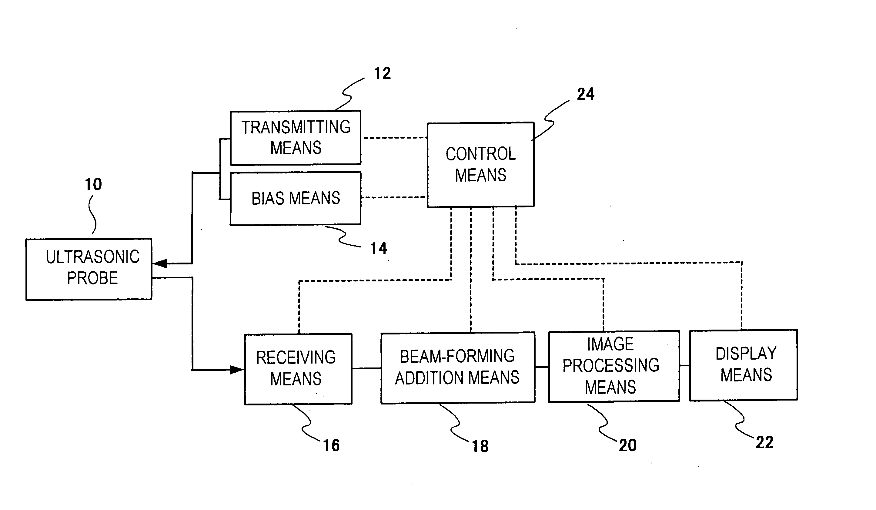
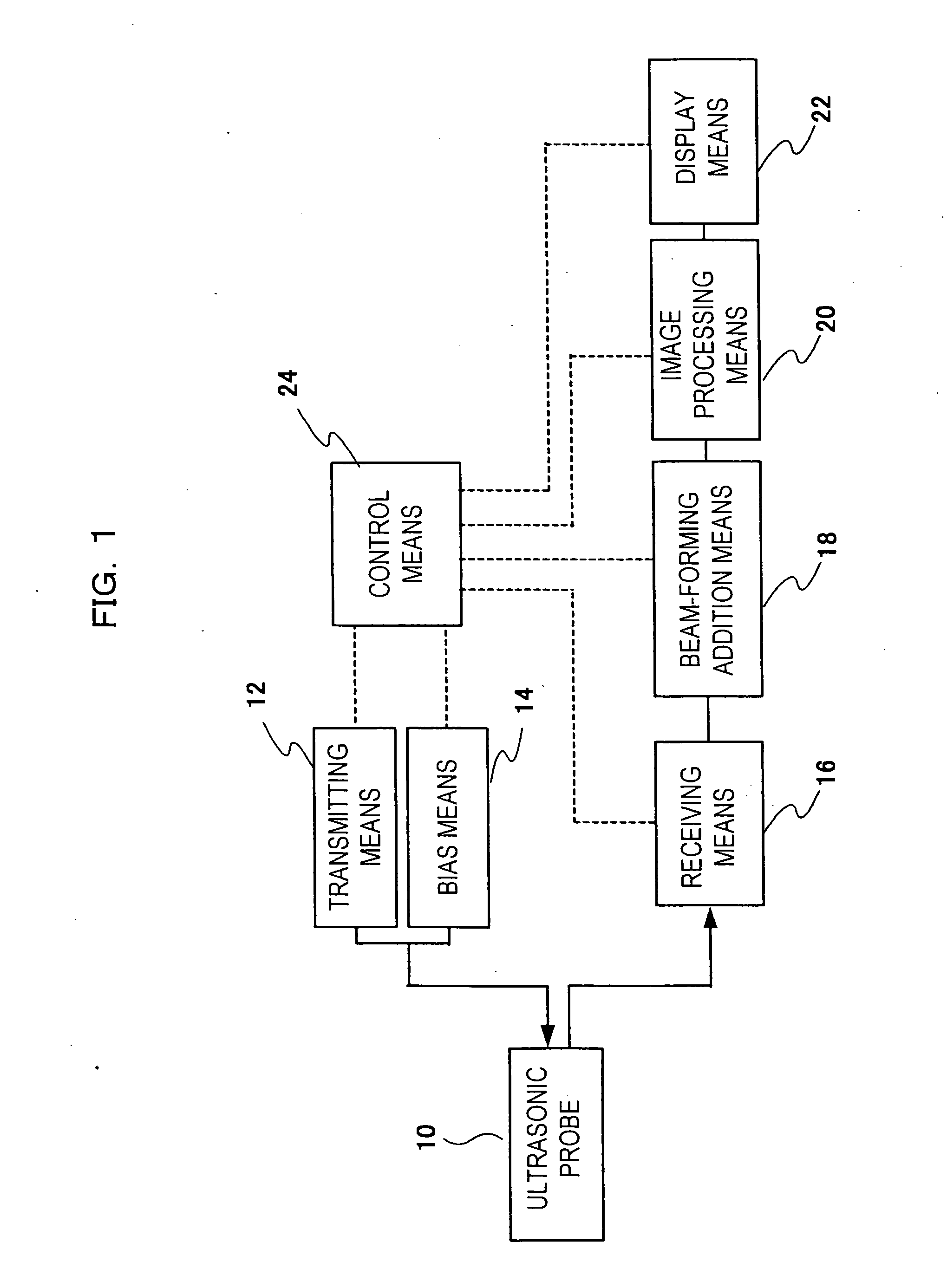
[0037] A description will be given of a first embodiment of an ultrasonic probe to which the present invention is applied and an ultrasonic imaging apparatus with reference to the drawings. FIG. 1 is a block diagram illustrating the configuration of an ultrasonic imaging apparatus of the first embodiment to which the present invention is applied.

[0038] As shown in FIG. 1, the ultrasonic imaging apparatus includes an ultrasonic probe 10 including an array of a plurality of transducers for converting drive signals into ultrasonic waves to transmit the waves to an object to be inspected and converting the waves into electrical signals to receive ultrasonic waves generated from the object, transmitting means 12 for supplying a drive signal to the ultrasonic probe 10, bias means 14 for applying a direct-current bias by superposing the bias on the drive signal supplied to the ultrasonic probe 10, receiving means 16 for processing an electrical signal (in the following, called a reflectio...

second embodiment

[0066] A description will be given of a second embodiment of an ultrasonic probe to which the present invention is applied and an ultrasonic imaging apparatus with reference to the drawings. The present embodiment is different from the first embodiment in the point that a plurality of groups (sections) of each transducer is further divided into a plurality of groups, and a different direct-current bias value is applied to each group. Accordingly, the description of the same portion as that of the first embodiment is omitted, and a description will be given on the different points. In this regard, a description will be given by adding the same letters and numerals to the mutually corresponding portions.

[0067]FIG. 8 is an explanatory diagram showing a sound-pressure distribution in a minor-axis direction of an ultrasonic beam by an ultrasonic imaging apparatus of the second embodiment to which the present invention is applied. As shown in FIG. 8, an transducer 70 is formed with a plu...

third embodiment

[0072] A description will be given of a third embodiment of an ultrasonic probe to which the present invention is applied and an ultrasonic imaging apparatus with reference to the drawings. The present embodiment is different from the first to the second embodiments in the point that a direct-current-bias applied section is changed in accordance with a focal depth. Accordingly, the description of the same portion as that of the first and the second embodiments is omitted, and a description will be given on the different points. In this regard, a description will be given by adding the same letters and numerals to the mutually corresponding portions.

[0073]FIG. 9 is an explanatory diagram showing a sound-pressure distribution in a minor-axis direction of an ultrasonic beam by an ultrasonic imaging apparatus of a third embodiment to which the present invention is applied. As shown in FIG. 9, an transducer 73 formed by a plurality of oscillation elements is divided into 7 sections P1 t...


PUM


Abstract

An ultrasonic probe 10 is formed by arranging a plurality of transducers 26a to 26m for converting drive signals into ultrasonic waves to transmit the waves to an object to be inspected, and receiving ultrasonic waves generated from the object to convert the waves into electrical signals. Each of the transducers 26a to 26m has a plurality of oscillation elements 34-1 to 34-30, and each of the oscillation elements 34-1 to 34-30 has a characteristic in which the electromechanical coupling coefficient changes in accordance with the strength of the direct-current bias applied by being superposed on the drive signals. Electrodes 35, 36, and 37 of each of the oscillation elements 34-1 to 34-30 are connected to terminals 49-1 and 49-2 to which the drive signals are applied.

Description

TECHNICAL FIELD [0001] The present invention relates to an ultrasonic probe for picking up an ultrasound image (for example, a diagnostic image) of an object to be inspected, an ultrasonic imaging apparatus, and an ultrasonic imaging method. [0002] An ultrasonic imaging apparatus transmits and receives ultrasonic beams to and from an object to be inspected by an ultrasonic probe, and reconstructs an ultrasound image based on electrical signals output from the ultrasonic probe. The ultrasonic probe is formed by arranging a plurality of ultrasonic transducers which convert electrical signals into ultrasonic waves and vice versa. [0003] In general, the transducers of this ultrasonic probe are formed by a piezoelectric material such as crystal, piezoelectric ceramics. Thus, the width of each transducer has a relatively large size (for example, a few millimeters) as a result of the manufacturing process, etc., of the piezoelectric material. Accordingly, the mutual distances among the plu...

Claims


Application Information

Patent Timeline
IPC IPC(8): A61B8/00B06B1/02
CPCB06B1/0207B06B2201/76B06B2201/51B06B1/0292G10K11/341
Inventor OSHIKI, MITSUHIROKANDA, HIROSHISHINOMURA, RYUICHI
Owner HITACHI MEDICAL CORP
Why Eureka
Try Eureka