
Ultrasonic apparatus for diagnosis and therapy

Inactive Publication Date: 2007-01-18
HITACHI LTD
View PDF7 Cites 14 Cited by
  • Summary
  • Abstract
  • Description
  • Claims
  • Application Information

AI Technical Summary

Benefits of technology

[0026] Thus configured, it is enabled to move an exposure of an ultrasound for a phase shift and that of an ultrasound for a diagnosis in conjunction with each other, and to reduce the exposure amount of the ultrasound.

Problems solved by technology

However, if because the HIFU therapy obtains an exposure positional selectivity only due to a convergence of an ultrasound, an aim is missed due to a body movement, there is a possibility that a high intensity ultrasound not less than 1 kW / cm2 is exposed on a target position other than a target position.
However, because a micro bubble cannot exist only in a blood vessel due to a restriction of a size thereof, it is difficult to restrict the bubble to a specific position of a tissue.
However, because a conventional ultrasonic apparatus for a diagnosis and therapy cannot start a therapy in conjunction with the production of a micro bubble from the phase-shift type ultrasound contrast agent, there is a problem that an ultrasound of a comparatively high intensity is requested to be exposed in producing the micro bubble from the contrast agent.

Method used


Image

  • Ultrasonic apparatus for diagnosis and therapy
  • Ultrasonic apparatus for diagnosis and therapy
  • Ultrasonic apparatus for diagnosis and therapy

Examples


example 1

[0104] In an example 1 is verified a phase-shift type ultrasound contrast agent in a case that a waveform of an ultrasonic pulse for a phase shift is changed. In the example 1, as the contrast agent was used an emulsion type agent disclosed in Ultrasound Contrast Image 92 (Proc. 4th Intern Symp.) by Kawabata et al. (2004) described before.

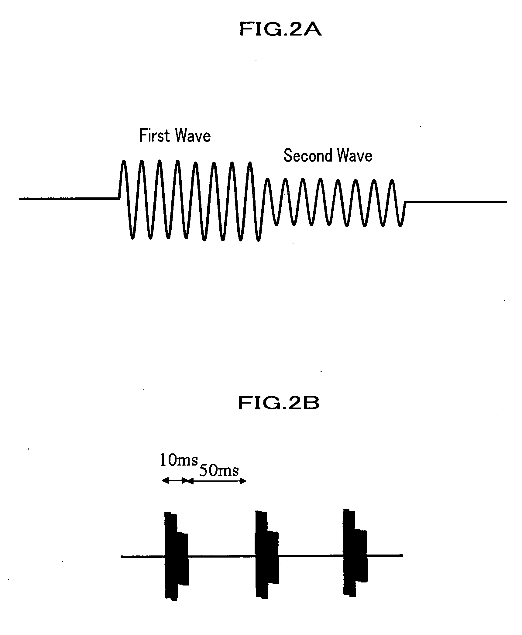
[0105]FIGS. 4A to 4D are drawings respectively verifying phase shift differences of a contrast agent in cases that waveforms of ultrasonic pulses for a phase shift are changed. Although in FIGS. 4A to 4D an acoustic intensity of a first wave is 4 W / cm2 (temporal averaged) in common, a second wave is changed to a predetermined acoustic intensity. Meanwhile, an ultrasound frequency is 3.4 MHz in both of the first and second waves.

[0106] As shown in FIGS. 4A to 4C, in cases that the second wave is not less than 1 W / cm2 with respect to 4 W / cm2 of the first wave, it was enabled to detect the phase shift even if the acoustic intensity of the second wav...

example 2

[0108] In an example 2 was practically performed a diagnosis and therapy, using the ultrasonic apparatus 1 of the embodiment. An object for the diagnosis and therapy is colon 26 tumor subdermally implanted in a mouse.

[0109] As a contrast agent was used the emulsion type agent disclosed in Ultrasound Contrast Image 92 (Proc. 4th Intern Symp.) by Kawabata et al. (2004) described above.

[0110] In addition, for the diagnosis was used an ultrasonic pulse of 7.5 MHz; for the phase shift, an ultrasonic pulse of 3.4 MHz and 4 W / cm2 (temporal averaged) (10 ms ON, 50 ms OFF); and for the therapy, an ultrasonic pulse of 3.4 MHz and 50 W / cm2 (temporal averaged) (10 ms ON, 50 ms OFF). Meanwhile, in the example 2 was not scanned the ultrasound for the phase shift.

[0111]FIG. 5 is a drawing in the example 2 showing one example of diagnostic images displayed in a display device; (B1) and (B4) are diagnostic images of a B mode used in a general ultrasound diagnosis; and (P1), (P2), (P3), and (P4) a...


PUM


Abstract

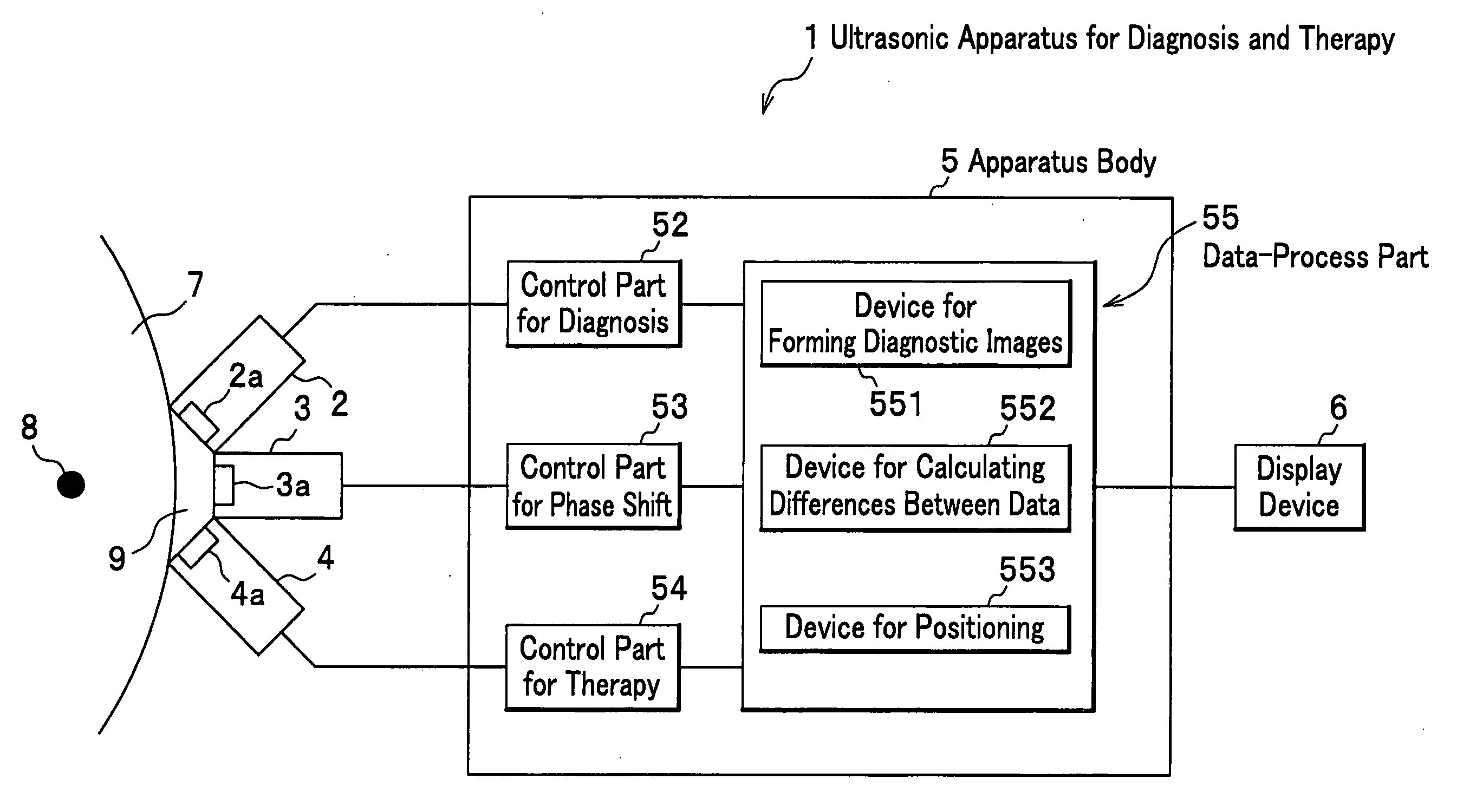
The ultrasonic apparatus for a diagnosis and therapy includes: a first ultrasound probe, a second ultrasound probe, and an ultrasound exposure apparatus for exposing ultrasounds for a phase shift, diagnosis, and therapy, respectively; an echo detection device for detecting an ultrasound echo; control parts for the phase shift for causing the shift in an ultrasound contrast agent by exposing the ultrasound for the shift through the first device, and for the diagnosis for detecting the shift of the agent, using the echo detected by the detection device, corresponding to an exposure of the ultrasound for the diagnosis by the second device; a difference calculation device for calculating a difference over time of the shift detected by the control part for the diagnosis; a device for positioning for deciding a target position where the difference is produced; and a control part for the therapy for exposing the ultrasound for the therapy to the decided target position through the exposure apparatus.

Description

CROSS REFERENCE TO RELATED APPLICATIONS [0001] The present application claims priority from Japanese application 2005-144367, filed on May 17, 2005, the content of which is hereby incorporated by reference into this application. BACKGROUND OF THE INVENTION [0002] 1. Field of the Invention [0003] The present invention relates to an apparatus for a diagnosis and therapy utilizing an ultrasound, and particularly, to the apparatus for the diagnosis and therapy utilizing the ultrasound used in combination with a phase-shift type ultrasound contrast agent. [0004] 2. Description of the Related Art [0005] It is a long time since image diagnostic modalities such as an X-ray CT (Computed Tomography) apparatus, an MRI (Magnetic Resonance Imaging) apparatus, and an apparatus for a diagnosis and therapy became an indispensable tool in clinical settings. These are something where differences of a CT value, a spin relaxation time, and an acoustic impedance within a living body are imaged, respecti...

Claims


Application Information

Patent Timeline
IPC IPC(8): A61B8/00
CPCA61B8/08A61N7/02A61B2019/5276A61B8/481A61B2090/378
Inventor KAWABATA, KENICHISUGITA, NAMIUMEMURA, SHINICHIRO
Owner HITACHI LTD
Learn More