
Broadcast receiving apparatus

Inactive Publication Date: 2007-01-18
ARUZE CORP
View PDF3 Cites 77 Cited by
  • Summary
  • Abstract
  • Description
  • Claims
  • Application Information

AI Technical Summary

Benefits of technology

[0012] Additional objects and advantage of the invention will be set forth in the description which follows, and in part will be obvious from the description, or may be learned by practice of the invention. The objects and advantages of the invention may be realized and obtained by means of the instrumentalities and combinations particularly pointed out hereinafter.
[0013] The accompanying drawings, which are incorporated in and constitute a part of the specification, illustrate embodiments of the invention, and together with the general description given above and the detailed description of the embodiments given below, serve to explain the principals of the invention.
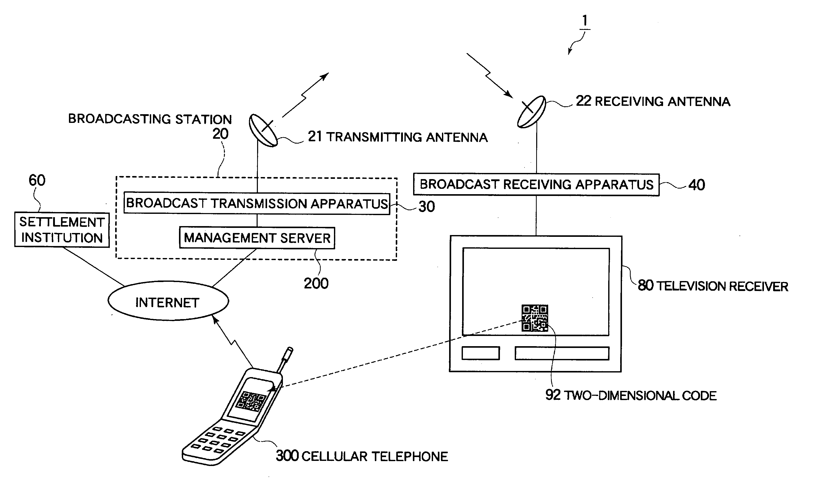
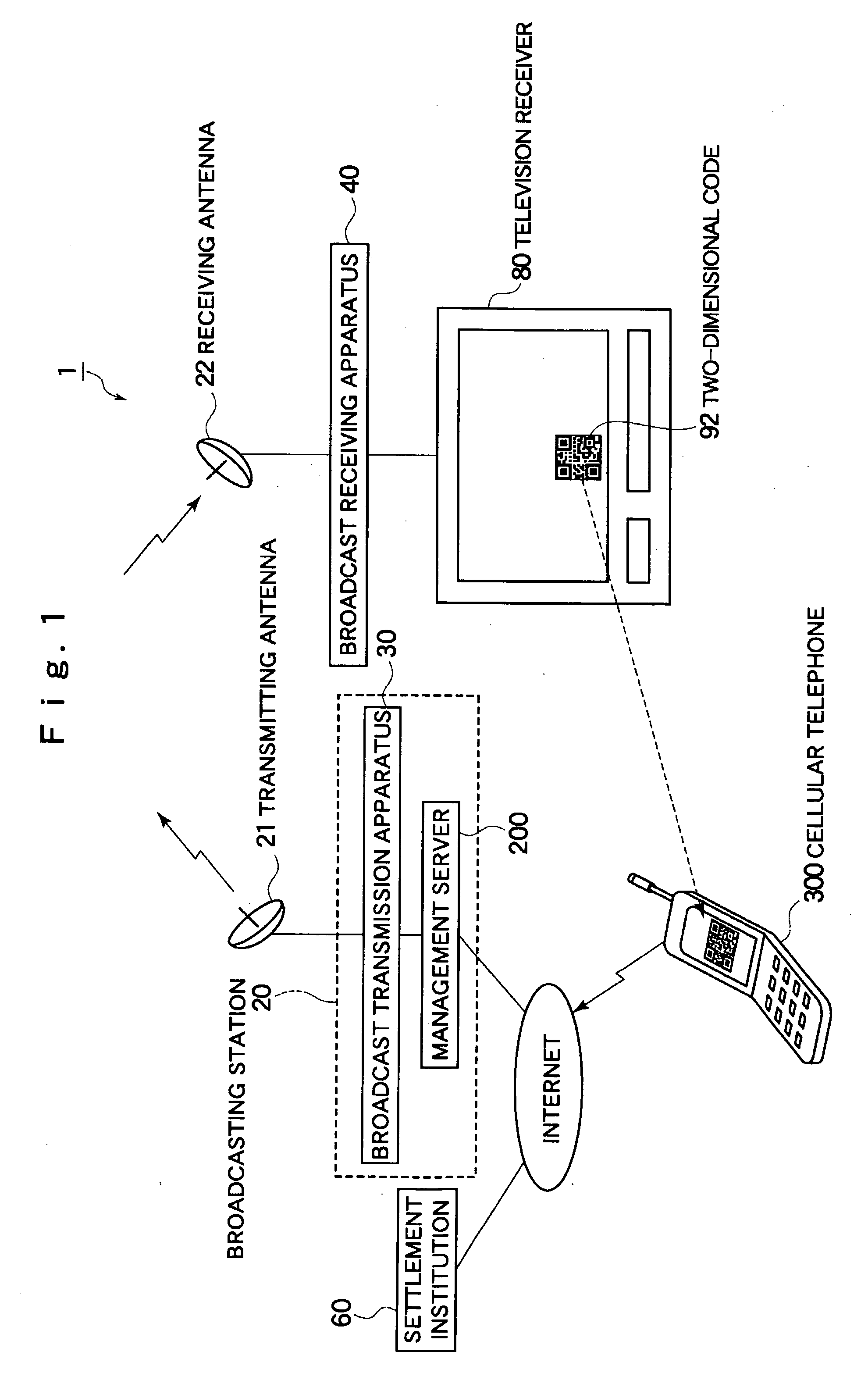
[0014]FIG. 1 is a configuration diagram showing an example of a broadcast transmission system according to an embodiment;
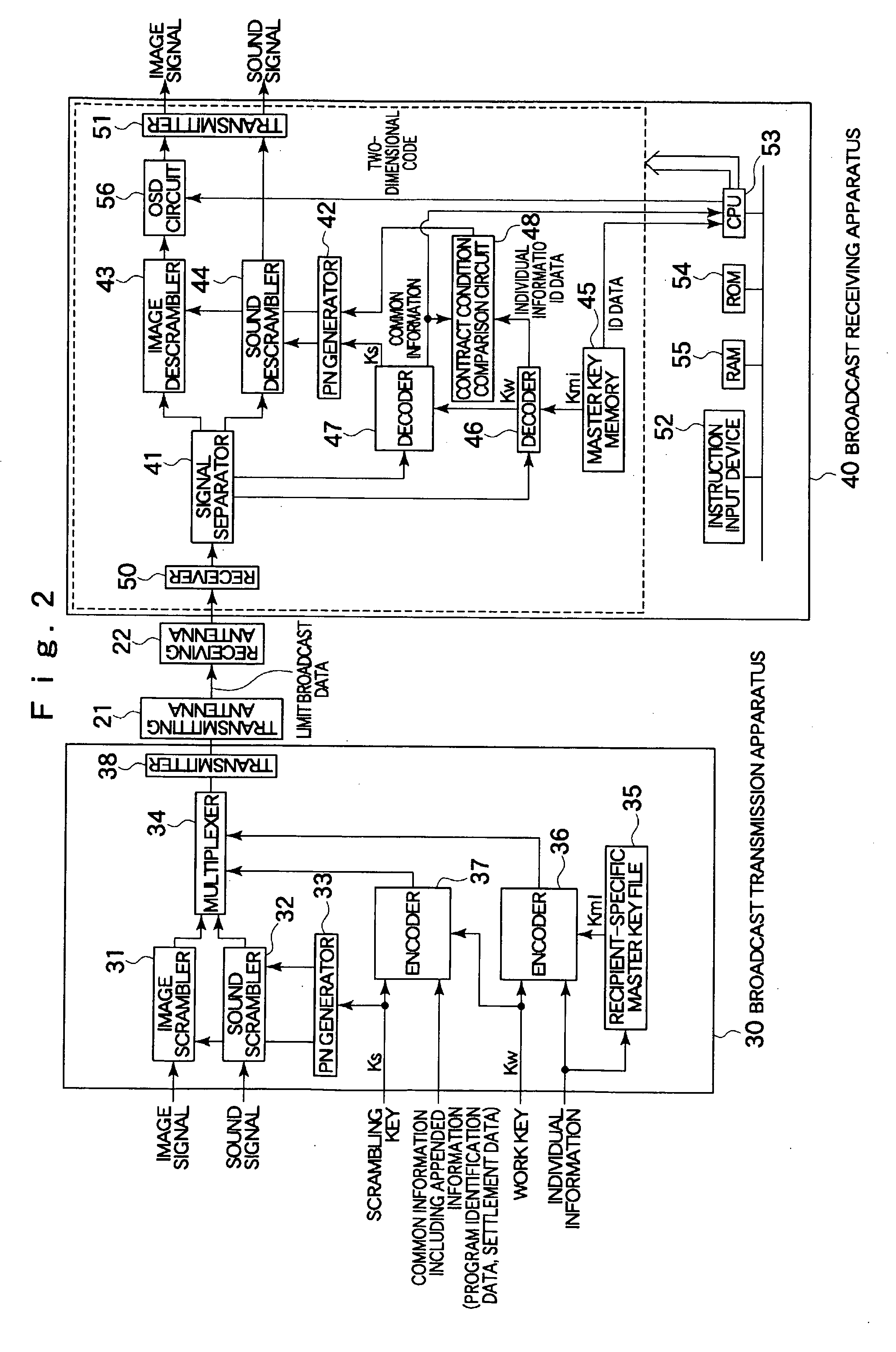
[0015]FIG. 2 is a block diagram showing an internal configuration of a broadcast transmission apparatus and a broadcast receiving apparatus shown in FIG. 1;
[0016]FIG. 3 is a block diagram showing an internal configuration of a management server shown in FIG. 1;
[0017]FIG. 4 is a block diagram showing an internal configuration of a cellular telephone shown in FIG. 1;

Problems solved by technology

However, a problem has existed that in order to separately install a cable modem etc., for carrying out data communication, it is necessary to secure an installation space.
Also, with a broadcast receiving apparatus with a built-in cable modem mentioned in Japanese Unexamined Patent Publication No. 2004-254102, which has been conceived from the space-saving point of view, a recipient who does not use the two-direction communication function frequently has hesitated to purchase due to its high price in comparison with a non-built-in kind apparatus, which causes eventually a problem that the two-direction communication function cannot be used at all.

Method used


Image

  • Broadcast receiving apparatus
  • Broadcast receiving apparatus
  • Broadcast receiving apparatus

Examples


Embodiment Construction

[0022] A broadcast receiving apparatus according to an embodiment comprises a memory storing ID data which identifies the broadcast receiving apparatus, an appended information receiver which receives appended information appended to a broadcast from a broadcasting station, a generator which generates code information obtained by encoding the ID data stored in the memory and the appended information received by the appended information receiver, and a transmitter which transmits the code information generated by the generator to a display connected outside.

[0023] According to such a configuration, the code information generated from the ID data which identifies the broadcast receiving apparatus (for example, a set top box) and the appended information received from the broadcasting station is transmitted to the display (for example, a television receiver) connected to the exterior.

[0024] As the code information includes the ID data which identifies the broadcast receiving apparatu...


PUM


Abstract

To provide a broadcast receiving apparatus which enables an effective use of information appended to a broadcast, even though a two-direction communication function is not furnished. A broadcast receiving apparatus includes: a memory storing ID data which identifies the broadcast receiving apparatus; an appended information receiver which receives appended information appended to a broadcast from a broadcasting station; a generator which generates code information obtained by encoding the ID data stored in the memory and the appended information received by the appended information receiver; and a transmitter which transmits the code information generated by the generator to a display connected outside.

Description

RELATED APPLICATION [0001] This application claims the priority of Japanese Patent Application No. 2005-202773 filed on Jul. 12, 2005, which is incorporated herein by reference. BACKGROUND OF THE INVENTION [0002] 1. Technical Field [0003] The present invention relates to a broadcast receiving apparatus. [0004] 2. Related Art [0005] Heretofore, a system where a television signal is transferred via a satellite, such as a broadcast satellite or a communication satellite, and a cable line, and received in each household, has been widely known. A broadcast receiving apparatus (for example, a set top box) for the purpose of enabling viewing of a broadcast from the received television signal, is installed in a residence of a recipient using the system. As well as image data and sound data related to the broadcast, information appended to the broadcast details is included in the television signal received by the broadcast receiving apparatus and, when the recipient operates the broadcast re...

Claims


Application Information

Patent Timeline
IPC IPC(8): H04N7/16H04N7/18H04N5/44H04N7/173
CPCG06Q20/145G06Q20/32G06Q20/3276G07F17/16H04N7/162H04N7/17318H04N2007/1739H04N21/41407H04N21/4223H04N21/4227H04N21/4622H04N21/4782H04N21/6181H04N21/2543
Inventor OKADA, KAZUOFUJIMOTO, JUN
Owner ARUZE CORP
Learn More