
Masonry wall system

a masonry wall and system technology, applied in the direction of structural elements, building components, construction materials, etc., can solve the problems of affecting the use of fasteners on masonry wall construction, and requiring complex mold manufacturing

Inactive Publication Date: 2007-01-25
GRAY CALVIN
View PDF6 Cites 23 Cited by
  • Summary
  • Abstract
  • Description
  • Claims
  • Application Information

AI Technical Summary

Benefits of technology

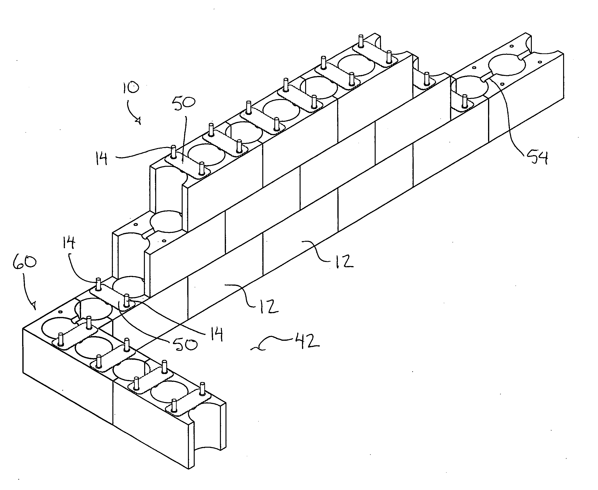
[0011] By providing fastener apertures which are spaced apart from one another in a lateral direction extending between the opposing upright side walls of the block, the support area joining each block to the previous row is wider across the thickness of the wall structure to more evenly anchor each block to the previous rows. Furthermore the fasteners joining the rows are mounted closer to the outer walls under tension so that the fasteners provide better support to resist bending forces of the wall in either lateral direction.
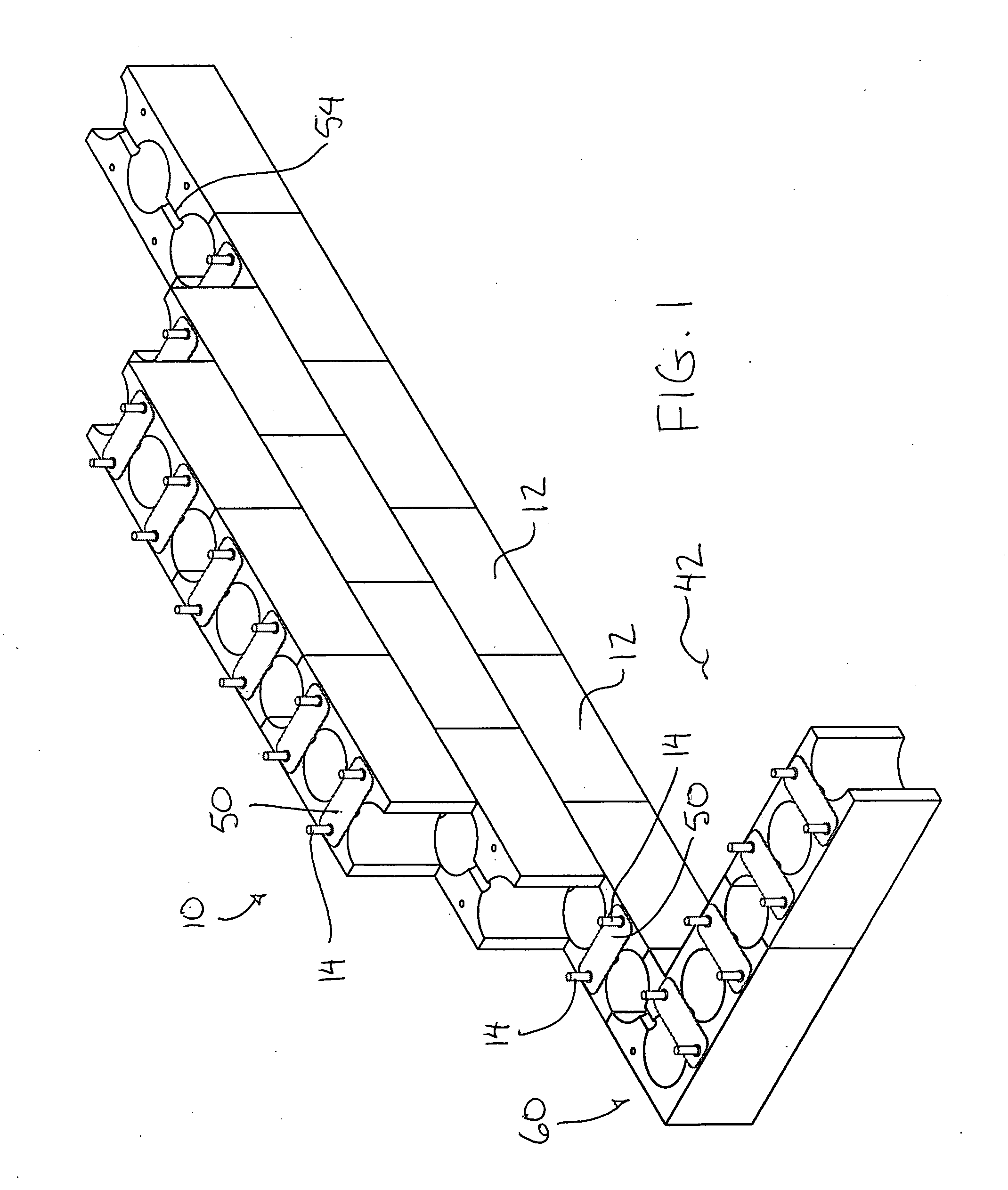
[0017] Construction of the block to include a pair of webs spanning between opposing side walls to define a central conduit therebetween and a pair of partial conduits at the ends of the block, results in an advantageous location of the fasteners in the webs being located approximately a quarter of the length of the block from each end of the block. In this configuration each block is connected to a pair of adjacent and overlapped blocks in the previous row by a fastener which is centrally located within the area of overlap between the blocks for optimum distribution of loads.
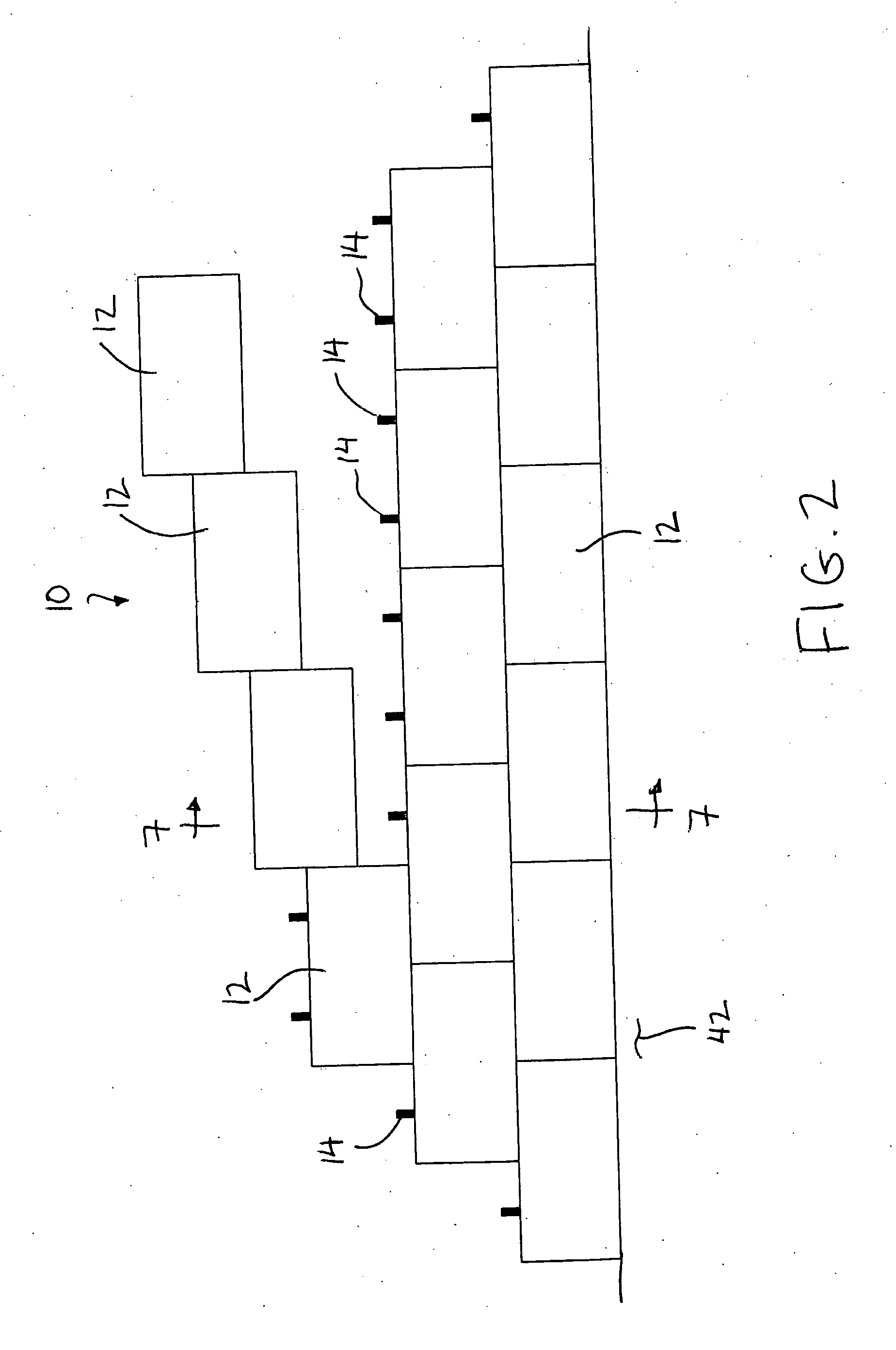
[0025] The fasteners described herein are suitably arranged to span only a single row of blocks in the preferred embodiment. In this arrangement a much simpler block construction can be used as the blocks do not require any additional interlocking or alignment mechanism to connect to the previous row other than simply aligning the fasteners from one row to the next. The simplicity of the block design reduces manufacturing costs of the block when only fastener apertures are required and the top and bottom faces of the block can remain substantially flat and free of complex interlocking shapes. The fasteners are much easier to align with a previous row of fasteners when assembling only a single row at a time.
[0055] The masonry wall system of the present invention (or mortarless block wall) possesses numerous benefits and advantages over the traditional masonry wall construction. Most significantly, the mortarless block wall can be built without the specialized skills and knowledge of a mason. As well, the mortarless block wall can be constructed in any weather conditions without affecting its structural integrity (unlike traditional masonry wall construction that is effected by weather condition that in turn affects its structural integrity such as frozen mortar in cold weather, baked mortar in hot weather or dried mortar in windy weather). As well, as the mortarless block wall is constructed it has immediate structural strength (unlike conventional masonry construction, which only has strength after the cement mortar has cured). Having instantaneous strength is beneficial when the walls are exposed to construction in windy conditions. Another benefit to the mortarless block wall is that the construction can be de-constructed by simply reversing the construction process. The masonry block units and the metal connectors can be re-used over and over again.
[0058] Another advantage of the mortarless masonry block is that it has large continuous vertical holes in the center. These holes can be used for installing plumbing lines, electrical conduits and other building services and won't get plugged with mortar or concrete when installed due to the use of the masonry fasteners according to the present invention.

Problems solved by technology

Traditional masonry units have vertical chases or conduits for installing plumbing lines, electrical conduits and other building services, but the vertical holes are often small and are commonly filled with cement grout or concrete and thus very often not continuous from top to bottom.
The blocks thus require complex molds for manufacturing.
This relative movement is typically undesirable in a large static structure.
The configuration of the cleats would interfere with the use of the fasteners on a masonry wall construction.

Method used


Image

  • Masonry wall system
  • Masonry wall system
  • Masonry wall system

Examples


Embodiment Construction

[0071] Referring to the accompanying figures there is illustrated a masonry wall system generally indicated by reference numeral 10. The system 10 includes a plurality of masonry blocks 12 which are mechanically coupled to one another using masonry fasteners 14 as described herein.

[0072] Each masonry block 12 comprises a rectangular body of pre-cast concrete which is elongate in a longitudinal direction between opposing ends 16 of the body. The height and width in a lateral direction perpendicular to the longitudinal direction are approximately equal to one another, having dimensions each of approximately 200 millimetres while the length is approximately double. The blocks each include opposing, upright and flat side walls 18 extending longitudinally between the ends and which form the surfaces of the wall structure being formed when the blocks are stacked on top of one another. Each block also includes a flat top side 19 and a flat bottom side 20 which permits stacking of the bloc...


PUM


Abstract

The masonry block wall system comprises masonry blocks fastened together with interconnecting threaded steel fasteners. Four fasteners on each block connect with a pair of identical blocks immediately above and a pair of identical blocks immediately below the block. The resulting masonry wall is structurally sound and allows large vertical chases or conduits for electrical, plumbing and the like. Unlike conventional masonry, the construction of the present masonry wall does not require specialized knowledge and skill of a mason and is relatively easy to build. As well, the masonry wall system is not dependent upon weather during construction and can be de-constructed without demolition.

Description

FIELD OF THE INVENTION [0001] The present invention relates to a masonry wall system in which masonry blocks are interconnected using threaded mechanical fasteners. BACKGROUND [0002] Masonry block walls are presently constructed using concrete blocks stacked on top of each other. The blocks are bonded together using cement mortar (both in the horizontal and vertical joints). A wire-reinforcing ladder is installed in the periodic horizontal joints. Construction of a masonry block wall requires a skilled mason. The construction of a masonry block wall requires a controlled environment while the cement mortar cures. [0003] In conventional masonry construction, the designer (the design engineer) has few means of knowing that the block wall is built in accordance with the designers specifications, for example: the mortar being correctly installed and having adequate strength, the concrete filled cores being completely filled and the reinforcing steel being placed correctly or being insta...

Claims


Application Information

Patent Timeline
Patent Type & Authority Applications(United States)
IPC IPC(8): E04C2/04
CPCE04B2/30E04C5/165E04C5/161E04B2002/0254
Inventor GRAY, CALVIN
Owner GRAY CALVIN
Learn More